Part of the New Holland Repair Manuals.
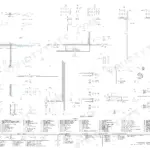
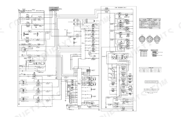
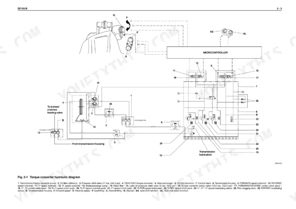
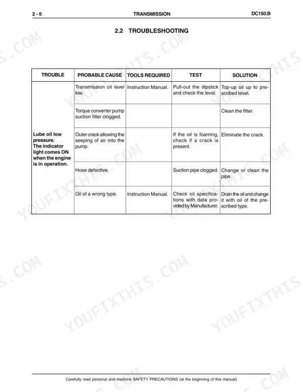
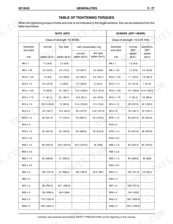
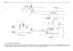
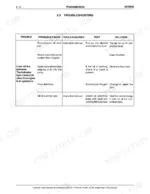
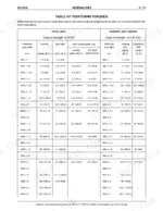
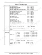
A transmission pressure fault on the DC150.B crawler dozer is traced in the transmission troubleshooting section of this 375-page New Holland DC150.B service manual PDF, issued under OEM ID 603.67.081.00. Hydraulic schematics lay out the transmission, brake and steering circuits, and the dozer equipment section follows oil from pump and control valve to the blade lifting and ripper cylinders; an electrical schematic maps fuses, relays, diode boxes and connectors. Other chapters run from engine mounting and clutch overhaul to final drive removal, track chain tension, wear limits and refrigerant charging. Tightening torques sit in their own table. Check transmission pressure at 13.75 ± 0.5 bar with 10 lt/min flow, rising to 17.0 ± 0.5 bar at 70 lt/min. Your parts order for the 500-hour service starts with the delivery filter. Section bookmarks and a searchable text layer lead from troubleshooting chart to pressure check, so you finish the transmission repair to New Holland's own figures.
What's Inside This Manual
| System | Pages | Key Topics |
|---|---|---|
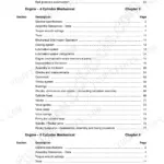
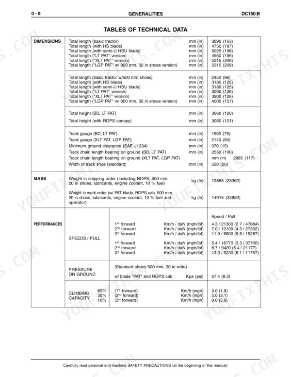
| Generalities | 5-48 | Safety Rules, Identification Data, Table of Fluid Capacities, Table of Centre of Gravity, Main Dimensions and Weights, Tables of Technical Data, Check Data on the Machine |
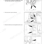
| Engine | 49-60 | General Specifications, Engine Identification, Design Features, Serviceability, Engine Mounting |
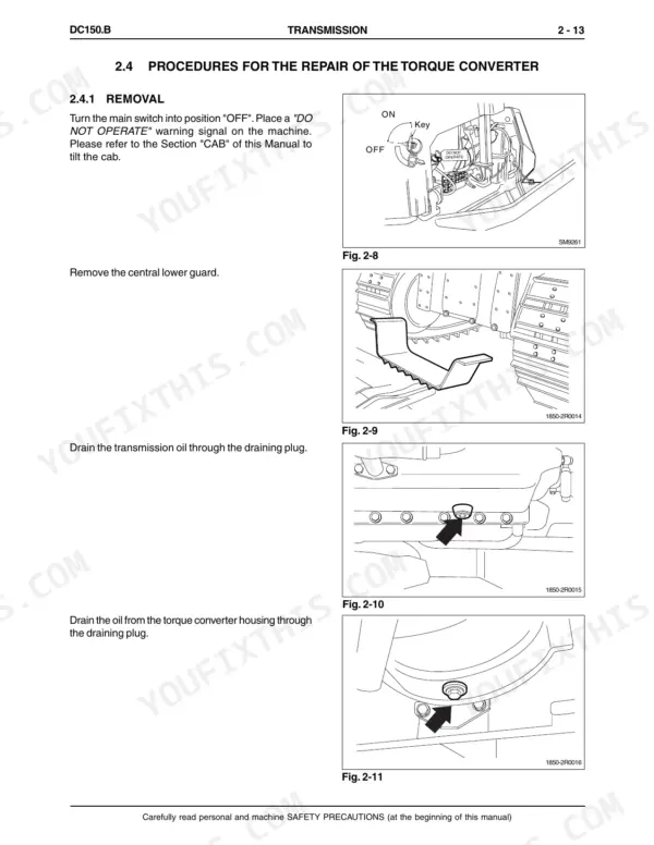
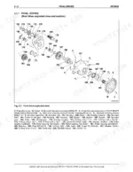
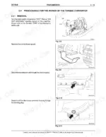
| Transmission | 61-130 | General Description, Troubleshooting, Torque Converter, Clutch Overhaul, Special Tools |
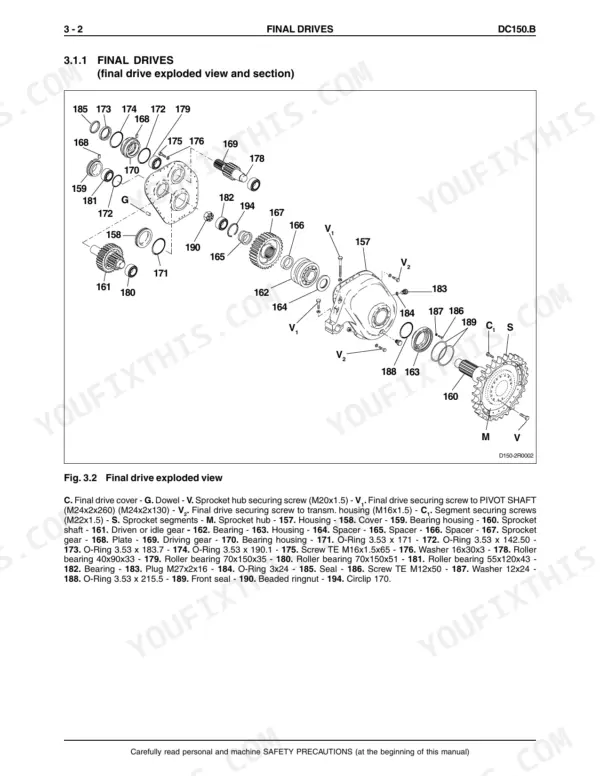
| Final Drives | 131-154 | General Description, Final Drive Removal, Housing Cover, Gear Shaft, Front Seals, Special Tools |
| Brakes and Steering Differential | 155-256 | Brakes Hydraulic System, Steering Hydraulic System, Brake Pedal Valve, Steering Side Group, Bevel Gear Set, Special Tools |
| Undercarriage | 257-290 | Track Chain Tension, Idler, Track Chain Support Rollers, Bottom Rollers, Track Tensioner Device, Wear Limits |
| Dozer Equipment Hydraulic System | 291-320 | Hydraulic Circuit, Hydraulic Oil Tank, Equipment Hydraulic Pump, Hydraulic Control Valve, Blade Lifting Cylinder, Ripper Cylinder |
| Electrical System | 321-348 | Electric Diagram, Fuses, Instrument Panel, Monitor Senders, Display, Relay Group |
| Air Conditioning Unit | 349-373 | Operating Instructions, Technical Data, Service Precautions, Refrigerant Charging, Leak Inspection, Troubleshooting |
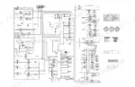
| Electrical Schematic | 374-375 | Fuses, Relays, Diode Boxes, Diverter Box, Connectors, Starter Motor |
Quick Reference Specifications
| Specification | Value | Page |
|---|---|---|
| Operating pressure | 31.5 to 35.0 bar (456.9 to 507.6 psi) | p. 35 |
| Transmission pressure (at flow of 10 lt/min, 2.6 gpm) | 13.75 ± 0.5 bar (3.6 ± 0.1 psi) | p. 26 |
| Transmission pressure (at flow of 70 lt/min, 18.5 gpm) | 17.0 ± 0.5 bar (4.5 ± 0.1 psi) | p. 26 |
| Maximum pressure (equipment/steering) | 190/350 bar (2755.7/5076.3 psi) | p. 35 |
| Delivery filter replacement interval | 500 hours | p. 165 |
| Delivery filter nominal rating | 30 µ | p. 165 |
| Transmission/torque converter oil filter tightening torque | 4 daNm (29.5 ft lb) | p. 128 |
| Transmission/torque converter oil filter by-pass valve setting | 2.5 bar (36.25 psi) | p. 128 |
| Securing screws, front bearing stop | 4.1 to 4.9 daNm (30.24 to 36.14 ft lb) | p. 119 |
| Securing screws, shaft hub stop | 4.1 to 4.9 daNm (30.24 to 36.14 ft lb) | p. 119 |
| Machine Services Link Fuse | 50 Amp | p. 328 |
| Alternator Link Fuse | 80 Amp | p. 328 |