Part of the New Holland Repair Manuals.
The New Holland E26C Service Manual (part number 51605673, June 2019) takes the E26C Cab and Canopy mini excavator apart one system at a time. It runs from the Kubota D1305 engine down to the rubber tracks. In between it covers pump adjustment, the main control valve, swing and travel motors, the swivel, EPPR auxiliary valves, cylinders, the quick coupler and the swing bearing.
A machine sitting with a slow travel motor or a dead work light costs a crew a day of guessing. This book gives you the test pressures, connector tables and rebuild steps.
The sections follow the way a shop works: engine, hydraulics, undercarriage, electrical, then boom, dipper, blade and cab. Large electrical and hydraulic foldout schematics sit at the end.
What's Inside This New Holland E26C Manual
| System | Pages | Key Topics |
|---|---|---|
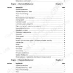
| Introduction and Specifications | 1-53 | Applicability, Safety Rules, Machine Specifications, Weights and Dimensions, Consumables, Product Identification, Service Precautions |
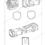
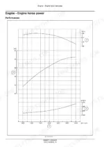
| Engine | 54-181 | Engine Specifications, Compression Testing, Cylinder Heads, Oil Pan and Covers, Crankshaft and Flywheel, Pistons and Connecting Rods, Valve Drive and Gears |
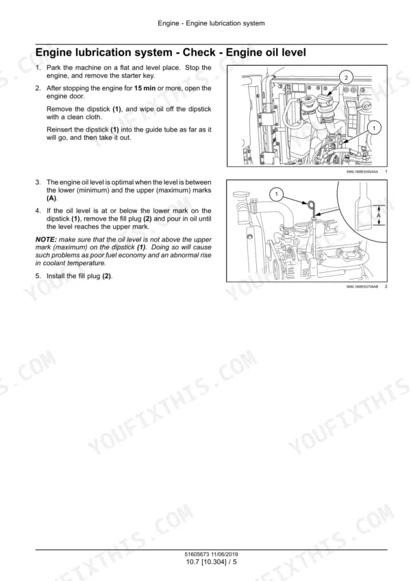
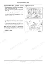
| Engine Lubrication and Cooling | 182-219 | Engine Oil Level, Oil Pressure, Oil Pump, Crankcase Ventilation, Coolant Replacement, Radiator, Water Pump, Thermostat |
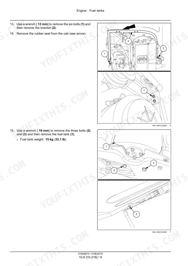
| Engine Fuel, Air Intake and Exhaust | 220-309 | Fuel Tank, Air Cleaners, Fuel Filters, Injection Pump, Injectors, Throttle Linkage, Intake and Exhaust, Fan Drive |
| Hydraulic Systems | 310-365 | Hydraulic Schemas, Pilot Circuit, Boom, Arm and Bucket Circuits, Swing and Travel Circuits, Pressure Release, Drift Testing, Troubleshooting |
| Variable Displacement Pump and Reservoir | 366-417 | Pump Construction, Disassembly and Inspection, Pump Adjustment, Delivery and Relief Pressure Tests, Pilot Pressure, Oil Reservoir, Oil Cooler |
| Main Control Valve and Pilot Controls | 418-571 | Main Control Valve, Relief Valve Functions, Right and Left Hand Controls, Optional Proportional Controls, Dozer Lever, Lever Force and Stroke Tests |
| Swing System | 572-629 | Swing Motor, Swing Reduction Gear, Parking Brake, Removal and Installation, Disassembly and Assembly, Motor and Brake Tests, Troubleshooting |
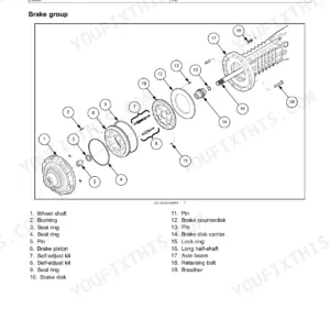
| Travel System | 630-691 | Travel Motor, Travel Reduction Gear, Two-Speed Operation, Brake and Counterbalance Valves, Disassembly and Assembly, Pressure Tests, Troubleshooting |
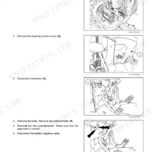
| Swivel, Pedals and Auxiliary Hydraulics | 692-773 | Hydraulic Swivel, Travel and Swing Pedals, Pilot Solenoid Block, Pilot Accumulator, Hammer and Shears Selector, Auxiliary Circuits, EPPR Valves |
| Hydraulic Cylinders | 774-869 | Boom, Dipper, Bucket, Swing Arm and Dozer Cylinders, Quick Coupler, Holding Valves, Cylinder Inspection and Rebuild |
| Frames and Ballasting | 870-889 | Swing Bearing, Counterweight, Additional Counterweight, Installation Torques |
| Tracks and Track Suspension | 890-933 | Rubber Tracks, Track Tension, Drive Sprockets, Idler, Recoil Spring, Carrier Roller, Lower Track Rollers |
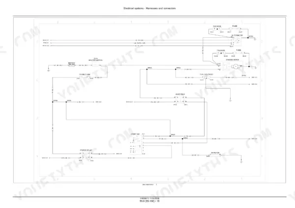
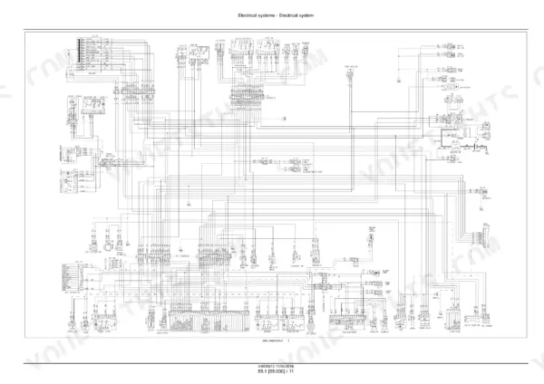
| Electrical Systems and Circuit Schemas | 934-1041 | Component Identification, Power and Starting Circuits, Charging Circuit, Monitoring Circuit, Lighting Circuits, Auxiliary Controls, Anti-Restart Circuit |
| Engine Sensors and Switches | 1042-1071 | Fuel Level Sensor, Coolant Temperature and Overheat Sensors, Oil Pressure Switch, Air Cleaner Restriction Sensor, Warning Lamp Troubleshooting |
| Harness Locations | 1072-1085 | Undercarriage, Upper Structure, Cab, Canopy and EPPR Harnesses, Intermediate Connector Locations |
| Electrical Schematic Sheets | 1086-1115 | Legend, Battery and Starting, Power Distribution, Grounding, Lighting, Washer and Wiper, Cluster, Accessories, HVAC, Audio and Options |
| Wire Connectors, Fuses and Relays | 1116-1215 | Connector Component Diagrams, Connector Tables with Pin, Wire and Color-Size Columns, Schematic Sheet References, Fuse and Relay Box |
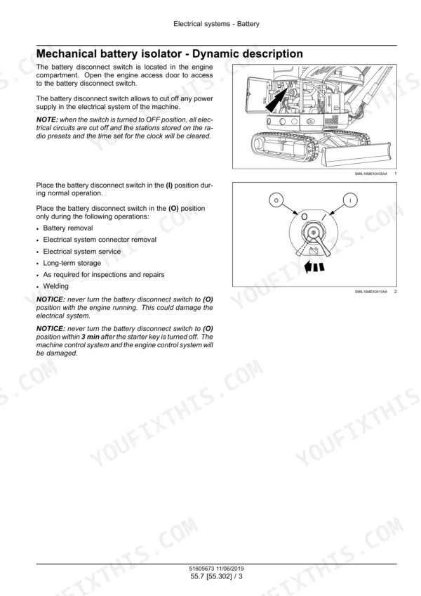
| Battery, Starting, Charging and Instruments | 1216-1331 | Battery Service, Engine Starter, Glow Plug System, Alternator, Lighting, Instrument Cluster, Washer and Wiper, Safety and Speed Controls |
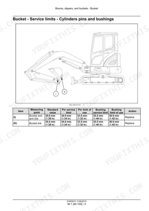
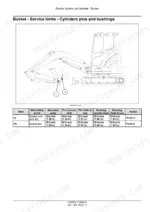
| Boom, Dipper, Bucket and Dozer Blade | 1332-1383 | Bucket and Linkages, Boom Pivoting Support, Dipper Arm, Boom, Dozer Blade, Pins and Bushings |
| Platform, Cab and Bodywork | 1384-1473 | Engine Hood, Protections and Footboards, Operator Seat, Cab, Interior Trim, Side Shields, Cab Controls, Service Menu |
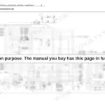
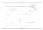
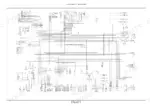
| Foldout Electrical and Hydraulic Schematics | 1474-1477 | E26C - E30C Electrical Schematic Sheets 1/2 and 2/2, Hydraulic Schematic Sheets 1/2 and 2/2 |
Quick Reference Specifications
| Specification | Value | Page |
|---|---|---|
| Engine model | Kubota D1305 | p. 24 |
| Piston displacement | 1261 cm³ (77 in³) | p. 24 |
| Compression ratio | 24 : 1 | p. 24 |
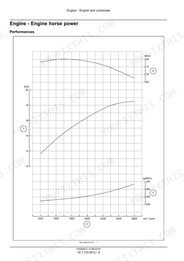
| Maximum torque at 1600 RPM | 81.4 N·m (60 lb ft) | p. 24 |
| Engine oil quantity | 5.7 L (1.5 US gal) | p. 24 |
| Engine coolant | 5 L (1.3 US gal) | p. 45 |
| Total capacity of the hydraulic system | 55 L (14.5 US gal) | p. 45 |
| Operating weight - Cab version | 2580 kg (5688 lb) | p. 26 |
| Operating weight - Canopy version | 2430 kg (5357 lb) | p. 26 |
| Rubber track shoe width | 250 mm (9.8 in) | p. 25 |
| Ground pressure - Cab version | 31.7 kPa (4.6 psi) | p. 25 |
| Ground pressure - Canopy version | 29.6 kPa (4.3 psi) | p. 25 |
| Maximum digging depth (boom 1.945 m, arm 1.120 m) | 2420 mm (95.3 in) | p. 29 |
| Maximum digging reach (boom 1.945 m, arm 1.120 m) | 4480 mm (176.4 in) | p. 29 |
| Main pump rated oil flow | 2 x 27 L/min (7.1 US gpm) | p. 24 |
| Overload relief valve pressure | 23538 kPa (3414 psi) | p. 24 |
| Swing motor relief pressure | 16671 kPa (2418 psi) | p. 25 |
| Travel motor relief pressure | 21573 kPa (3129 psi) | p. 25 |
| Travel motor brake release pressure | 1861 kPa (270 psi) | p. 25 |
| Counterweight bolts torque | 470.0 - 635.0 N·m (346.7 - 468.4 lb ft) | p. 886 |