
Part of the New Holland Repair Manuals.
Five service manual volumes for the New Holland TD65F, TD75F and TD85F tractors, all covering the same three machines, delivered together in one ZIP download. The set holds print 84574094A dated 19/10/2016 at 943 pages, print 84574094 dated 15/08/2013 at 828 pages, the earlier revision of the same print number, print 47913163 at 609 pages, print 48064954 at 613 pages, and print 84285941 at 503 pages in the older SECTION 00 / SECTION 10 style, 3,496 pages across the five files. The fullest volume is 84574094A, with 17 sections and the only Cab Climate Control section in the set, and the section list on this page describes that volume.
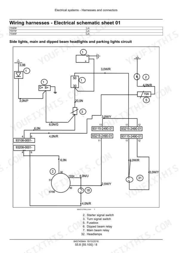
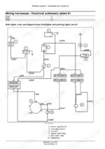
Its electrical coverage runs as numbered schematic sheets, each sheet one circuit with its own component key. Sheet 01 on page 903 carries the side lights, main and dipped beam headlights and parking lights circuit, with wire gauges and colour codes written on every run, the fusebox, the dipped and main beam relays, and harness part numbers on the connector blocks.
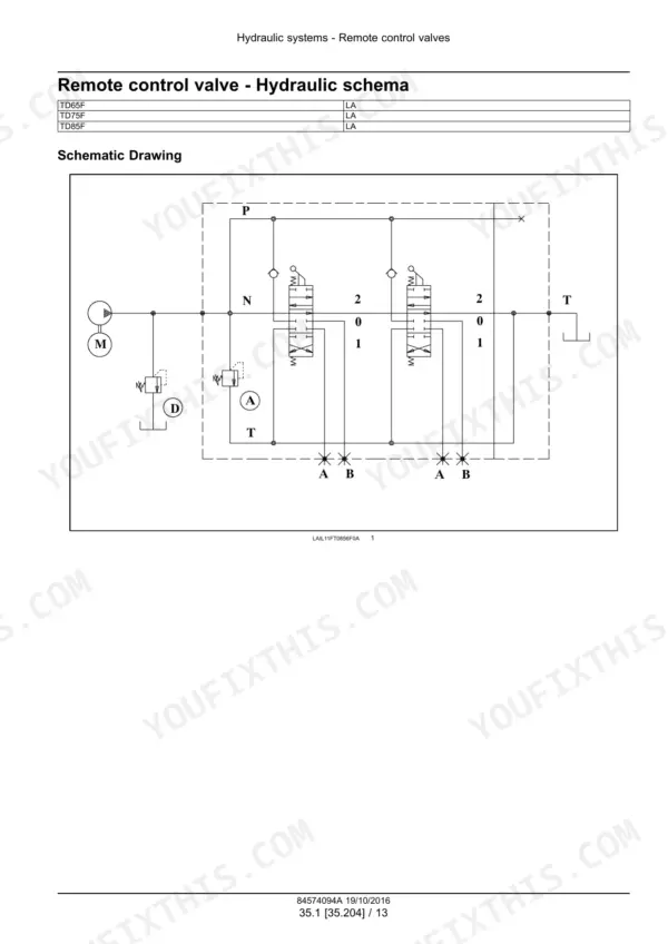
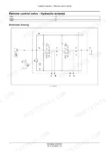
The hydraulic drawing is per component rather than a whole-machine circuit: page 634 shows the remote control valve schema, with the pump, relief valve and two three-position spool sections and their A and B service ports. These tractors are the Latin-America build family, and the volumes carry the LA market marker and the Curitiba, Brazil publications address.
Other editions of this manual
- New Holland TD65F, TD75F, TD85F Service Manual — Wiring Diagrams Original price was: $61.99.$39.99Current price is: $39.99.
- New Holland TD65F, TD75F, TD85F Service Manual — Wiring Diagrams Original price was: $53.99.$39.99Current price is: $39.99.
What's Inside This New Holland TD65F, TD75F, TD85F Manual
| System | Pages | Key Topics |
|---|---|---|
| Contents & Introduction | 1-32 | Section and Subsection Numbering, Safety Notices, Torque and Fastener Standards |
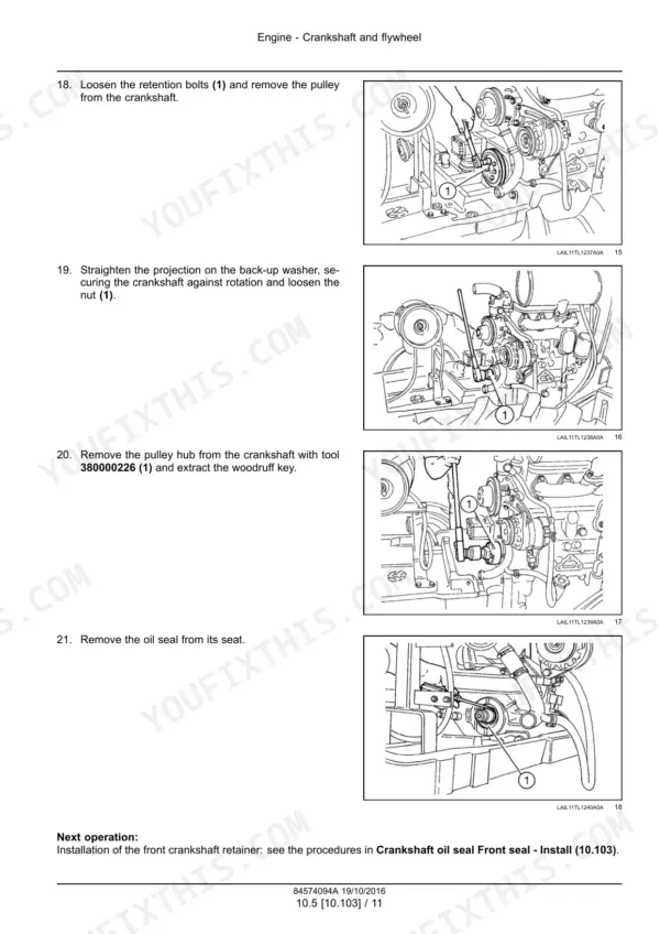
| Engine - 10 | 33-206 | Engine and Crankcase Overhaul, Cylinder Head and Valve Train, Lubrication and Cooling Circuits, Fuel Injection Pump and Injectors, Air Cleaner and Exhaust |
| Clutch - 18 | 207-248 | Clutch Removal and Installation, Release Bearing and Linkage, Adjustment and Free Play |
| Transmission - 21 | 249-348 | Gearbox Internal Components, 12x12 and 20x12 Layouts, Shift Controls and Linkage, Creeper Unit |
| Four-Wheel Drive (4WD) System - 23 | 349-372 | Drive Line and Propshaft, 4WD Engagement Clutch, Front Drive Housing |
| Front Axle System - 25 | 373-520 | Bevel Gear Set and Differential, Steering Knuckles and Swivel Housings, Final Drives and Hubs, Two-Wheel and Four-Wheel Drive Variants |
| Rear Axle System - 27 | 521-556 | Rear Differential, Planetary and Final Drives, Axle Shafts and Seals |
| Power Take-Off (PTO) - 31 | 557-578 | PTO Clutch Pack, Output Shaft and Guard, Speed Selection |
| Brakes & Controls - 33 | 579-620 | Service Brake Discs and Actuation, Park Brake, Pedal Linkage and Adjustment |
| Hydraulic Systems - 35 | 621-660 | Remote Control Valve with Its Hydraulic Schema Drawing, Pump and Regulated Low-Pressure System, Leakage Test, Sectional Views of the Valve |
| Hitches, Drawbars & Implement Couplings - 37 | 661-700 | Three-Point Linkage, Drawbar and Pick-Up Hitch, Lift Capacity Adjustment |
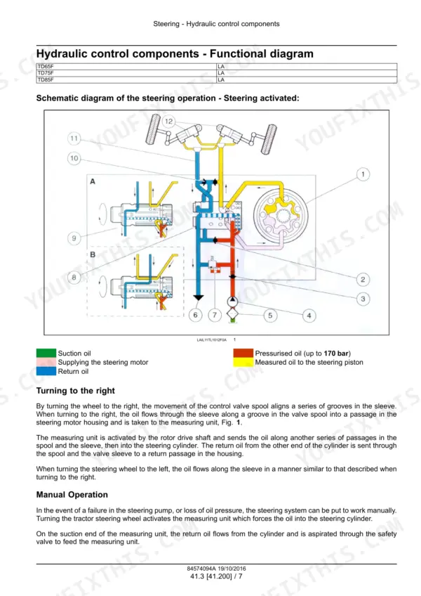
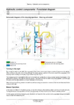
| Steering - 41 | 701-756 | Steering Pump, Hydrostatic Steering Unit, Steering Cylinder and Track Rods |
| Cab Climate Control - 50 | 757-818 | Heating and Ventilation, Air Conditioning Circuit, Blower, Controls and Filters |
| Electrical Systems - 55 | 819-910 | Electrical Schematic Sheets with Their Component Keys, Fuse and Relay Box Identification, Alternator and Starting Circuit, Instrument Cluster and Warning Circuits, Harness Routing by Build Variant |
| Platform, Cab, Bodywork & Decals - 90 | 911-935 | Cab and Platform Removal, Bonnet, Grille and Panels, Safety and Instruction Labels |
| Special Tool Index | 936-943 | Genuine Tool Part Numbers, Tools Referenced by Section |
New Holland TD65F, TD75F, TD85F Common Problems This Manual Covers
Headlights or parking lights stop working, and swapping bulbs and checking the obvious fuse does not fix it.
Work from the Electrical Systems section, pages 819-910. Start at schematic sheet 01 on page 903, which draws the side lights, main and dipped beam headlights and parking lights circuit with the wire gauge and colour code written on every run, so you can trace the exact wire. The same sheet locates the fusebox and the dipped and main beam relays, and its numbered key identifies the starter signal switch, turn signal switch and headlamps. Use the fuse and relay box identification pages in the same section to confirm which relay you are testing.
Manual Section: Electrical Systems - 55 p. 819A remote hydraulic outlet weeps oil, or an implement on the rear remotes slowly drops instead of holding.
Go to the Hydraulic Systems section, pages 621-660. It gives the remote control valve its own hydraulic schema on page 634, showing the pump, relief valve and both three-position spool sections with their A and B service ports, so you can see which spool feeds the leaking coupler. The section then provides a leakage test to confirm where the oil is going and sectional views of the valve to guide teardown and resealing of the affected spool section.
Manual Section: Hydraulic Systems - 35 p. 621Gears grind going into first from a standstill, or the clutch pedal has lost its free play and the clutch drags.
Use the Clutch section, pages 207-248. Start with the adjustment and free play procedure to restore the correct pedal travel, then check the release bearing and linkage, which the section covers as its own topic. If adjustment does not clear the drag, the same section walks through clutch removal and installation so you can inspect the driven plate and release components directly.
Manual Section: Clutch - 18 p. 207A growl or whine from the front end that appears when four-wheel drive is engaged and fades in 2WD.
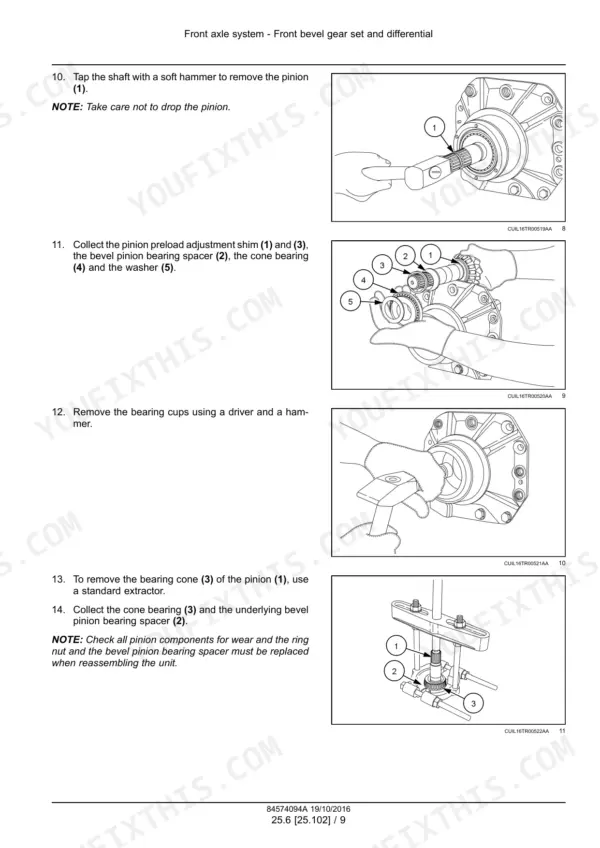
Check the driveline first in the Four-Wheel Drive (4WD) System section, pages 349-372, which covers the drive line and propshaft, the 4WD engagement clutch and the front drive housing. If the noise stays with the front axle itself, move to the Front Axle System section, pages 373-520, for the bevel gear set and differential, the steering knuckles and swivel housings, and the final drives and hubs, with the two-wheel and four-wheel drive variants treated separately.
Manual Section: Front Axle System - 25 p. 349Frequently Asked Questions
Why are there five volumes, and which one should I open first?
The ZIP holds five separate PDF service manual volumes for the same three tractors: prints 84574094A, 84574094, 47913163, 48064954 and 84285941. Open 84574094A first. It is the newest, dated 19/10/2016, the largest at 943 pages, and the only volume with a Cab Climate Control section. The 828-page 84574094 is the earlier 2013 revision of the same print number, and 84285941 uses the older SECTION 00 / SECTION 10 layout. You keep all five, so you can cross-check a procedure between revisions when a page in one volume does not match your tractor.
Does the manual include a full hydraulic circuit diagram for the whole tractor?
No, and it is better to know that before you buy. The hydraulic schema in this book is drawn per component: page 634 shows the remote control valve circuit, with the pump, relief valve and two three-position spool sections and their A and B service ports on the P, T and N lines. The Hydraulic Systems section (pages 621-660) also covers the pump and regulated low-pressure system, a leakage test, and sectional views of the valve, but there is no single whole-machine hydraulic foldout. p. 621
What do the electrical wiring diagrams look like?
The Electrical Systems section (pages 819-910) presents the wiring as numbered schematic sheets, 01, 02, 07 and others, each covering one circuit, with a schema index and a component key per sheet. Sheet 01 on page 903, for example, is the side lights, headlights and parking lights circuit, with wire gauges and colour codes marked on every run, such as 3,0B and 2,5W/Y, plus the fusebox, the dipped and main beam relays, and harness part numbers on the connector blocks. The section also covers fuse and relay box identification, the alternator and starting circuit, the instrument cluster, and harness routing by build variant. p. 896
Is the cab air conditioning and heating system covered?
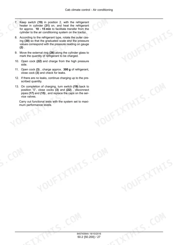
Yes, but only in one of the five volumes. Print 84574094A carries the Cab Climate Control section (pages 757-818), covering heating and ventilation, the air conditioning circuit, and the blower, controls and filters. None of the other four volumes has this section, which is one more reason to work from 84574094A as your main book. p. 757
My TD75F was built in Brazil. Is this the right manual for it?
Yes. The TD65F, TD75F and TD85F are orchard and vineyard specification utility tractors built for New Holland in Latin America, and these volumes carry the LA market marker and the Curitiba, Brazil publications address. The set covers the 2013-onward build family: the earliest print here is dated 15/08/2013 and the latest revision is dated 19/10/2016. The Electrical Systems section also documents harness routing by build variant. p. 1





Reviews
There are no reviews yet.