Part of the New Holland Repair Manuals.
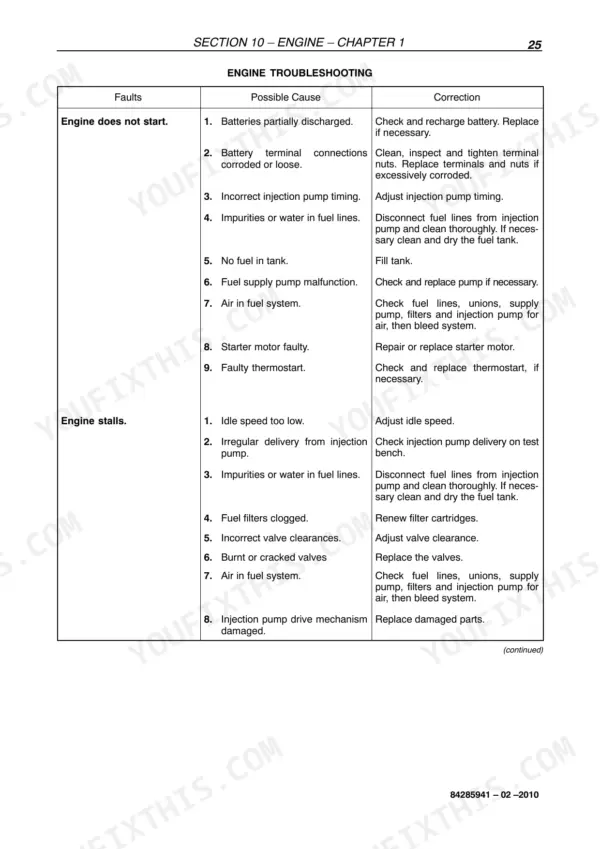
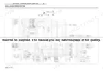
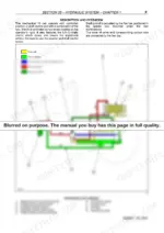
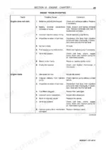
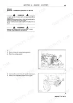
Engine, clutch, gearbox, rear axle, PTO, brakes, hydraulic lift, steering, and electrics: this New Holland TD65F, TD75F, TD85F service manual PDF (OEM 84285941) walks every one of those systems end to end across 503 pages of factory service procedure. Hydraulic schematics trace the rear lift circuit through each lift phase, and ten wiring diagram pages cover the tractor's electrical system alongside the instrument and component sections. Fault diagnosis tables open nearly every section, and the bench overhauls run from teardown through final adjustment, differential backlash included. Set injector opening pressure between 248 and 272 bar, then torque the fan and alternator pulley bolts to 55 Nm, straight from the spec tables. Planting doesn't wait while your tractor sits in the shed. Bookmarked and text-searchable, the file rides with you, from workshop bench to headland.
Other editions of this manual
What's Inside This Manual
| System | Pages | Key Topics |
|---|---|---|
| General | 10-15 | General Instructions, Safety Rules |
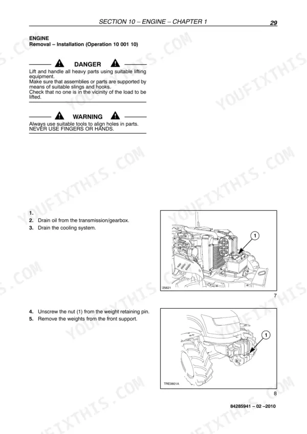
| Engine | 16-123 | Engine System (Injection Pump Calibration Data, Tightening Torques, Tools, Cross-Sectional Views, Lubrication and Cooling System Diagrams, Fault Diagnosis, Engine Removal-Installation, Engine Bench Overhaul, Checks, Measurements and Repairs, Radiator Removal-Installation, Crankshaft Front Oil Seal Removal Installation, Coolant Pump Removal Installation, Cooling System Thermostat, Bosch Injection Pump Removal Installation, Bosch Injection Pump Timing, Bosch Injection Pump Air Bleeding, Injectors Removal Installation, Valve Clearance Adjustment, Coolant Pump Overhaul, Compression Test) |
| Clutch | 124-149 | Clutches (Torque Settings, Tools, Section Views, Troubleshooting, Clutch - Removal-Installation, Dual Disk Clutch 11"/11" Test Bench Overhaul, Clutch Adjustments) |
| Gearbox | 150-189 | Mechanical Transmission (Main Data, Tightening Torques, Tools, Section Views, Description and Operation, Fault Diagnosis, Removal - Refitting) |
| Drive Lines | 190-205 | Main Specification, Torque Settings and Tools, Cross-Sectional Views, Transmission Shafts and Guard, Drive Gear Housing, Drive Gear Housing Removed |
| Front Axle Mechanical Transmission | 206-241 | Main Data, Tightening Torques, Tools, Cross-Sectional Views, Description and Operation, Complete Front Axle. Removal - Installation, Front Axle. Removal - Installation |
| Rear Axle and Transmission | 242-293 | Main Data, Tightening Torques, Special Tools, Cross-Sectional Views, Description and Operation and Troubleshooting, Transmission-Gearbox Casing Removal-Installation |
| Power Take-Off | 294-311 | Mechanical Power Take - Off (Main Specification, Tools, Torque Settings, Sectional Drawings, Description and Operation, Troubleshooting, Removal - Refitting, Bench Overhaul) |
| Braking System | 312-331 | Main Data, Tightening Torques, Cross-Sectional Views, Description & Operation, Tools - Troubleshooting, Service Brake Removal and Refitting, Removal-Refitting of Brake Pumps |
| Hydraulic System | 332-395 | Rear Mechanical Hydraulic Lift (Main Specification, Tightening Torques, Tools, Cross-Sectional Views, Description & Operation, Hydraulic Circuit, Description and Operation of Lift Phases, Fault Diagnosis, Hydraulic Lift - Disassembly Reassembly, Hydraulic Lift - Bench Overhaul, Linkage Adjustment, Pressure Relief Valve - Disassembly Reassembly, Pressure Relief Valve - Setting, Lift Control Valve - Disassembly Assembly and Overhaul on Bench, Lift Pump) |
| Steering | 396-429 | Principal Data, Tightening Torques, Section Views, Hydraulic Diagram, Operation, Fault Diagnosis, Tools, Hydrostatic Steering Control Valve - Removal-Installation |
| Electrical System | 430-503 | Instruments (Analogue Instruments Introduction, Transmitter and Switch), Components (Introduction, Component Description) |
Quick Reference Specifications
| Specification | Value | Page |
|---|---|---|
| All Models | ||
| Injector opening pressure | 248–272 bar (3596.9176–3945.0064 psi) | p. 20 |
| Injector protrusion relative to head face | 0.3 to 1.1 mm (0.0118 to 0.0433 in.) | p. 30 |
| Fan and alternator pulley bolts | 55 Nm (40.5659 ft lb) | p. 32 |
| Alternator and belt tension adjustment nut | 55 Nm (40.5659 ft lb) | p. 32 |
| Bolt or nut securing clutch / reverser casing to engine (C1) | 98 Nm | p. 159 |
| Sleeve cover retaining nuts (C2) | 17 Nm | p. 159 |
| Clearance between differential pinions and their pins | 0.080 – 0.122 mm | p. 207 |
| Differential lock control fork adjuster shim | 0.5 mm | p. 440 |
| Starter motor power | 2.5 kW | p. 440 |
| Maximum current drain without load | 60 A | p. 440 |
| TD65F | ||
| TD65F Bosch injection pump model | VE 3/12 F 1150 L-1118 | p. 20 |
| TD75F | ||
| TD75F Bosch injection pump model | VE 3/12 F 1150 L 1089 | p. 20 |