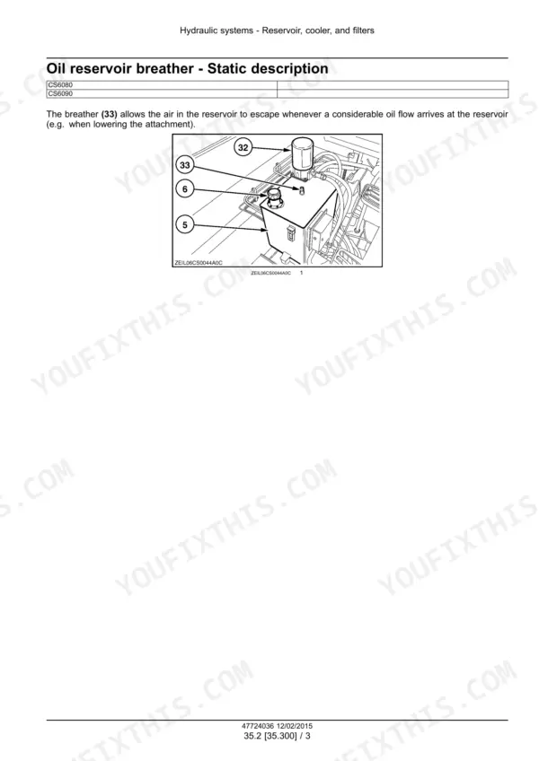
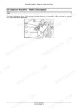
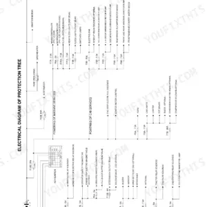
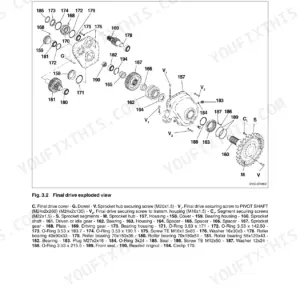
Part of the New Holland Repair Manuals.
Hydrostatic drive, transmission, feeder housing, threshing drum, rotary separator, cleaning system and grain tank unload: the New Holland CS6080 service manual PDF (OEM ID 47724036) works through each system of the CS6080 and CS6090 utility combines across 841 pages. Hydraulic schematics trace the circuit from the reservoir, cooler and filters through the variable displacement pump and main control valve out to the header height, tilting and leveling systems. Final drives, differential, service brakes, steering and air conditioning get chapters of their own. Check the low pressure filter bypass valve at 1.15 bar (17 psi), and torque M4 plated nuts to 2.9 N·m (25.7 lb in). If your job is the header height system, the schematic shows its connections back to the main control valve. Bookmarked and text-searchable, the PDF rides on a laptop or tablet right to the combine, open at the concave or tailings return while you work.
What's Inside This New Holland CS6080, CS6090 Manual
| System | Pages | Key Topics |
|---|---|---|
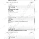
| Introduction | 7-26 | Foreword, Driveline Overview, Safety Rules, Product Overview, Basic Instructions, Torque, Conversion Factors |
| Engine - 10 | 27-44 | Engine Air Compressor |
| Main Gearbox and Drive - 14 | 45-64 | Main Gearbox and Drive |
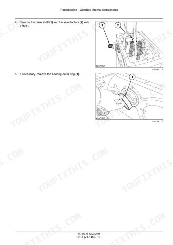
| Transmission - 21 | 65-140 | Mechanical Transmission, Mechanical Transmission External Controls, Gearbox Internal Components, Differential |
| Front Axle System - 25 | 141-160 | Final Drives |
| Rear Axle System - 27 | 161-172 | Planetary and Final Drives |
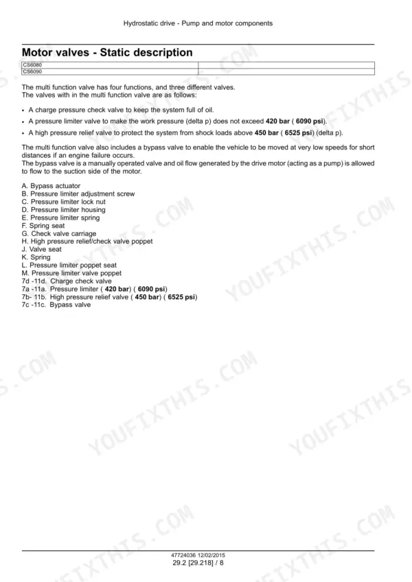
| Hydrostatic Drive - 29 | 173-234 | Transmission and Steering Hydrostatic Control, Pump and Motor Components, Hydrostatic Transmission |
| Brakes and Controls - 33 | 235-258 | Hydraulic Service Brakes |
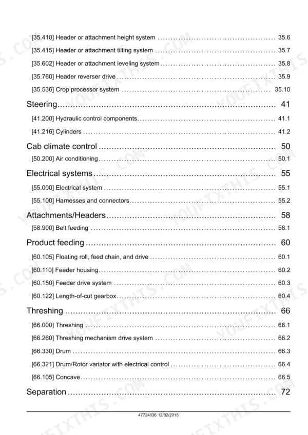
| Hydraulic Systems - 35 | 259-360 | Hydraulic Systems, Reservoir, Cooler, And Filters, Variable Displacement Pump, Main Control Valve, Safety and Main Relief Valves, Header or Attachment Height System |
| Steering - 41 | 361-386 | Hydraulic Control Components, Cylinders |
| Cab Climate Control - 50 | 387-428 | Air Conditioning |
| Electrical Systems - 55 | 429-468 | Electrical System, Harnesses and Connectors |
| Attachments/Headers - 58 | 469-482 | Belt Feeding |
| Product Feeding - 60 | 483-534 | Floating Roll, Feed Chain, And Drive, Feeder Housing, Feeder Drive System, Length-Of-Cut Gearbox |
| Threshing - 66 | 535-596 | Threshing, Threshing Mechanism Drive System, Drum, Drum/Rotor Variator with Electrical Control, Concave |
| Separation - 72 | 597-668 | Beater, Rotary Separator, Rotary Separator Drive System, Straw Walkers and Shafts |
| Cleaning - 74 | 669-786 | Cleaning, Cleaning Drive Systems, Grain Pan, Upper Shaker Shoe, Fan Housing, Fan Drive System, Tailings Return System |
| Crop Storage / Unloading - 80 | 787-837 | Clean Grain Elevator, Grain Tank Unload Drive System, Grain Tank Unload |
Quick Reference Specifications
| Specification | Value | Page |
|---|---|---|
| M3 Plated nut torque | 1.3 N·m (11.5 lb in) | p. 22 |
| M3 Lock nut torque | 0.7 N·m (6.2 lb in) | p. 22 |
| Pressure relief valve | 8 bar (116 psi) | p. 35 |
| Low pressure filter bypass valve setting | 1.15 bar (17 psi) | p. 283 |
| Gap Y | 2-3.5 mm (5/64 in - 1/8 in) | p. 506 |
| Dimension X | 5-7 mm (3/16 - 1/4 in) | p. 512 |
| Concave closing plate adjustment distance X | 1 - 4 mm (5/128 - 5/32 in) | p. 593 |
| Maximum input torque (Mechanical transmission) | 634 N·m | p. 68 |
| Maximum output torque (Mechanical transmission) | 2 x 4029 N·m | p. 68 |
| Brake disc diameter | 330 mm | p. 68 |
| Approximate total weight (Mechanical transmission) | 380 kg | p. 68 |
| Final drive to traction beam bolt torque | 440 N·m | p. 144 |
New Holland CS6080, CS6090 Common Problems This Manual Covers
New Holland CS6080 CS6090 pneumatic hitch valve, threshing clutch or unloading auger will not engage
Check that all bystanders are clear of the machine before operating any valve, per the warning on page 38. Turn the manual hitch control screw on the valve body 1/4 turn clockwise with a screwdriver to test the pneumatic system; if it engages manually, chase an electrical failure. Return the screw 1/4 turn counter-clockwise. The relief valve protects the circuit at 8 bar (116 psi), page 37.
Manual Section: Engine air compressor troubleshooting p. 38Threshing engagement clutch rotary union on the drum shaft suspected of leaking compressed air
Shut down, remove the key and relieve all system pressure before working on it (page 15). Remove the rotary union following Drum shaft Clutch - Remove (66.330). Connect port (1) to filtered, lubricated compressed air at 6 to 10 bar, close the other ports and immerse the union in an engine oil bath at about 20 °C (68 °F). Check for any leak for at least 5 s, as shown on page 41.
Manual Section: Engine air compressor troubleshooting p. 41Pneumatic hitch valve leaking air at the connection support after removal and reinstall
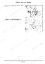
Push down the yellow lever, seat the valve (7) on the connection support (8), then release the lever. Reconnect the marked air hoses and the electrical connector, tightening the connector bolt. Close the drain at the bottom of the air tank reservoir, start the engine and check for air leaks following page 40. Never use your hands to check for leaks; use cardboard or wood (page 17).
Manual Section: Engine air compressor troubleshooting p. 40Hydrostatic transmission refill and start up, gauge not reaching minimum pressure while cranking
Chock traction and steering wheels front and rear, then disconnect connector (4) so the engine will not fire while cranking (page 219). Lift the rear wheels clear on powered rear axles. With the hydrostatic lever and gearshift in neutral, crank until the gauge shows at least 2.0 bar (29 psi), page 223. Then, everyone clear and never in a closed building, run low idle with the lever at half stroke two minutes each direction (page 224).
Manual Section: Hydrostatic Drive - 29 p. 223Front axle final drive mounting bolts to traction beam need correct torque after final drive removal
Install a safe support under the traction axle and use a supporting device rated for the heavy final drive (page 148). Apply LOCTITE 242 to the mounting bolts and torque them to 440 Nm (325 lb ft) following page 157. Torque the wheel nuts to 610 to 732 N·m and fill the final drive with 7.2 l of oil, per page 144.
Manual Section: Final drives troubleshooting p. 157Sensor wiring damaged or connector terminals dirty, bargraph and warning indicators on the monitor reading wrong
Shut the engine off before you couple or uncouple any connector, and never reach for connectors under the cab with the engine running (page 450). Clean terminals only by the method on page 450 and never with a trichloroethylene cleaner. Do not repair wire on sealed sensors; replace the sensor with a new one (page 464). Never apply 12 V directly to a solenoid (page 449).
Manual Section: Electrical system troubleshooting p. 450Frequently Asked Questions
What are the replacement specifications for the engine air compressor on the New Holland CS6080, CS6090?
The engine air compressor is protected by a pressure relief valve set to 8 bar (116 psi). If the pressure in the system reaches this level, the control valve is activated to protect the system. p. 37
What is the torque specification for the final drive cover bolt on the New Holland CS6080, CS6090?
The final drive cover bolt should be tightened to a torque between 28 - 45 N·m (21 - 33 lb ft). p. 144
What is the procedure for adjusting the drum anti-wrap plate?
To adjust the anti-wrap shields, loosen the two bolts on both sides of the drum. The shields must be installed with a dimension 'X' between 2 - 5 mm, measured with regard to the rasp bar with the largest radius. p. 569
What is the torque specification for the brake shoe with Allen bolts on the New Holland CS6080, CS6090?
The brake shoe with Allen bolts should be tightened to a torque between 260 - 270 N·m (192 - 199 lb ft). p. 239
What is the oil capacity of the final drive on the New Holland CS6080, CS6090?
The final drive gearbox has an oil capacity of 7.2 liters (1.9 US gal). p. 144
Do I get instant access to this New Holland CS6080 Service Manual?
Delivery is instant: a 841-page searchable PDF is yours the second checkout clears. Laptop, tablet, or phone, all fine.
Is this New Holland CS6080 manual print-friendly?
Yes. Print the sections you need to take out to the shop for your own use. Standard letter or A4 paper works.