Part of the New Holland Repair Manuals.
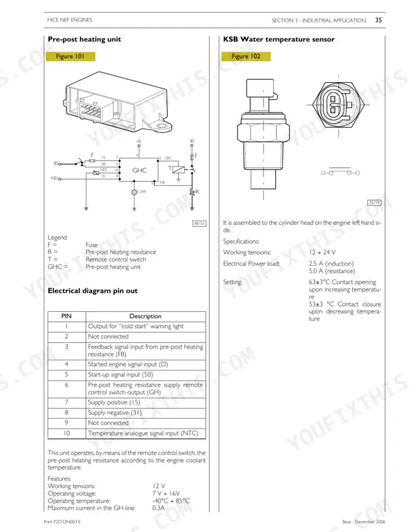
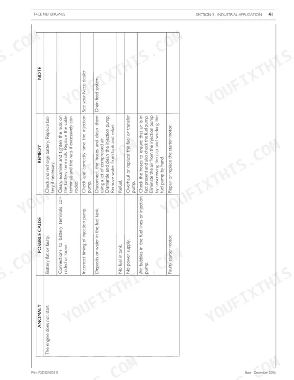
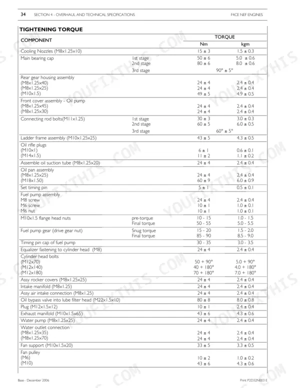
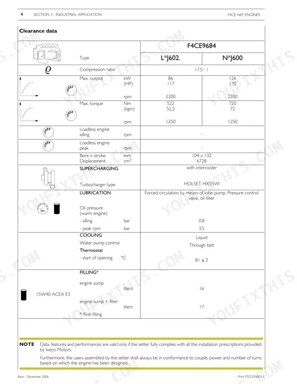
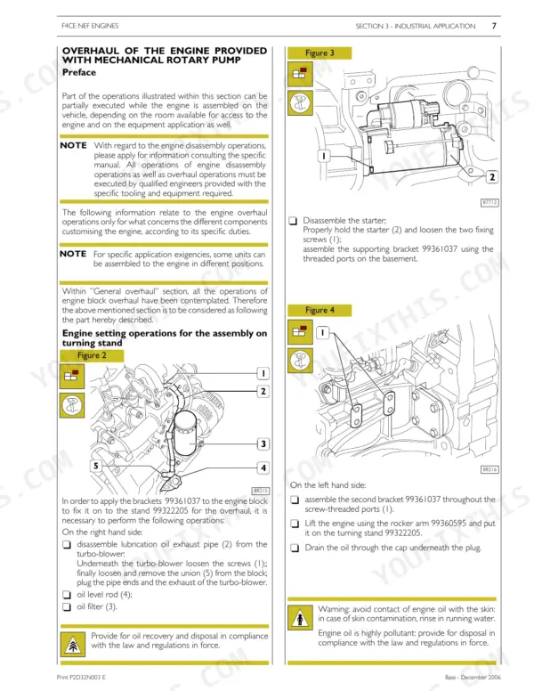
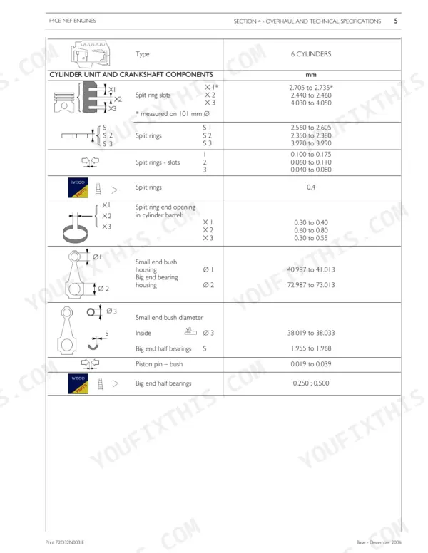
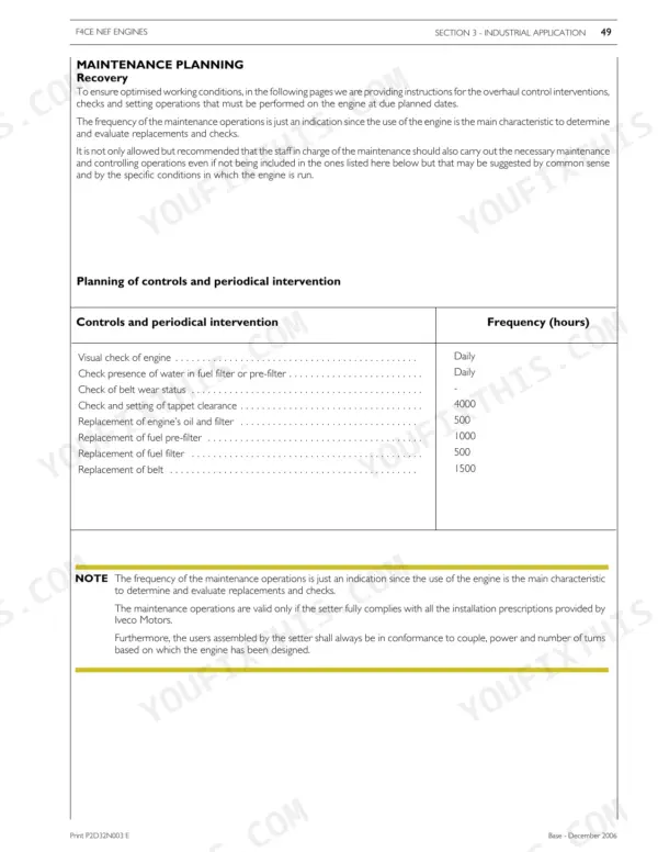
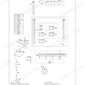
Take the engine down on a turning stand with injectors, manifolds and water pump off, following the 123-page New Holland TV6070 Iveco 6.7L F4CE NEF repair manual PDF, OEM 87491857. Overhaul data works through the cylinder unit, timing system, output shaft, rod and piston assembly and cylinder head, while wiring diagrams trace the starter, pre-post heating, KSB sensor and alternator circuits. Troubleshooting charts link starting faults, overheating, abnormal knocking and smoke colour to likely causes, and a maintenance schedule sets your oil, coolant and fuel filter intervals. Expect 90 A at 6000 rpm from a healthy alternator, and seat the starter to the gear case at 49 ± 5 Nm. Bookmarked, text-searchable pages keep the clearance data and torque tables close before it goes back together, and fastener callouts like M8x1.25x30 let you order the correct bolt the first time.
What's Inside This Repair Manual
| System | Pages | Key Topics |
|---|---|---|
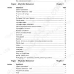
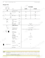
| General Specifications | 6-13 | Correspondence Between Technical Code and Commercial Code, Lubrication, Oil Vapour Recirculating System, Cooling System, Air Induction - Boost Diagram, Description |
| Fuel | 14-21 | Injection Feed System by Mechanical Rotary Pump, Feed Pump, Priming Pump, Fuel Filter |
| General Information and Mechanical Components Overview | 22-27 | Mechanical Components, Clearance Data, Engine Overhaul Preface, Turning Stand Operations |
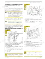
| Disassembly of Application Components | 28-35 | Supercharger, Fuel Filter, Injectors, Tappet Caps, Manifolds, Alternator, Thermostat, Water Pump |
| Installation of Application Components | 36-51 | Timing Gear, Cylinder Head, Flywheel, Oil Pan, Priming Pump, Fuel System Bleed, Power Takeoff |
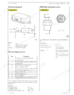
| Electrical Equipment | 52-59 | Electrical Component Layout, Cooling Liquid Temperature Sensor, Starter, Pre-Post Heating, KSB Sensor, Speed Sensor, Alternator |
| Troubleshooting | 60-67 | Engine Starting Issues, Engine Cuts Out, Engine Overheating, Irregular Operation, Abnormal Knocking, Smoke Analysis |
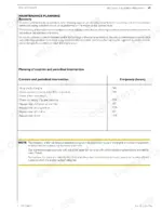
| Maintenance Planning and Procedures | 68-75 | Maintenance Schedule, Engine Oil Level Check, Cooling System Check, Fuel Filter Replacement, Alternator Belt Replacement |
| Overhaul and Technical Specifications | 76-111 | Cylinder Unit, Timing System, Output Shaft, Connecting Rod Piston Assembly, Cylinder Head |
| Tools | 112-119 | Tools List |
| Safety Prescriptions | 120-123 | Standard Safety Prescriptions |
Quick Reference Specifications
| Specification | Value | Page |
|---|---|---|
| All Models | ||
| Alternator working tension | 12 V | p. 58 |
| Alternator current delivered | 90A (at 6000 rpm) | p. 58 |
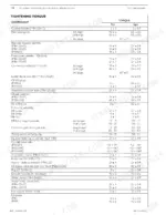
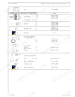
| Starter motor to gear case (M10) torque | 49 ± 5 Nm | p. 110 |
| Alternator to alternator support (M8x1.25x30) torque | 24 ± 4 Nm | p. 110 |
| Alternator to water inlet conn. assy (M8x1.25x30) torque | 24 ± 4 Nm | p. 110 |
| Fuel lift pump torque | 24 ± 4 Nm | p. 110 |
| Electrical tension for electrical connections | 48-60 V | p. 122 |
| Displacement | 6728 cm3 | p. 25 |
| Engine sump oil capacity | 16 liters | p. 25 |
| Engine sump + filter oil capacity | 17 liters | p. 25 |
| F4CE9684L*J602 | ||
| Max. output (L*J602) | 86 kW | p. 25 |
| F4CE9684N*J600 | ||
| Max. output (N*J600) | 126 kW | p. 25 |