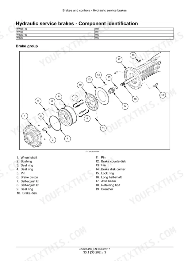
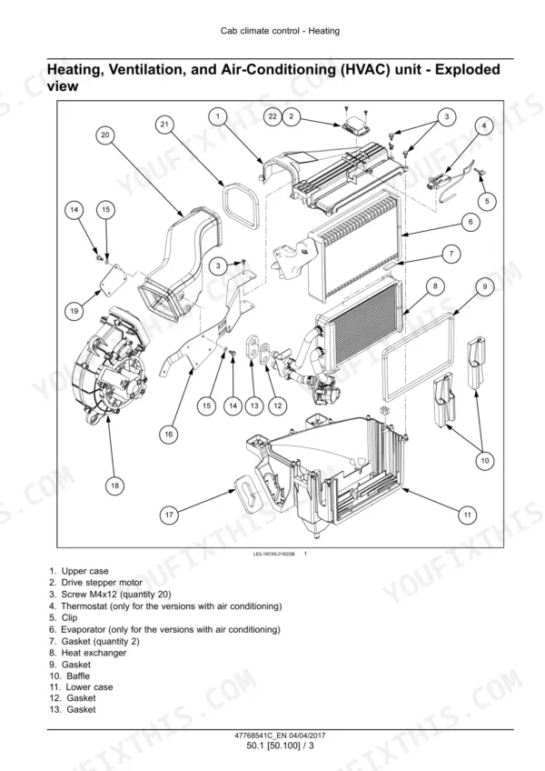
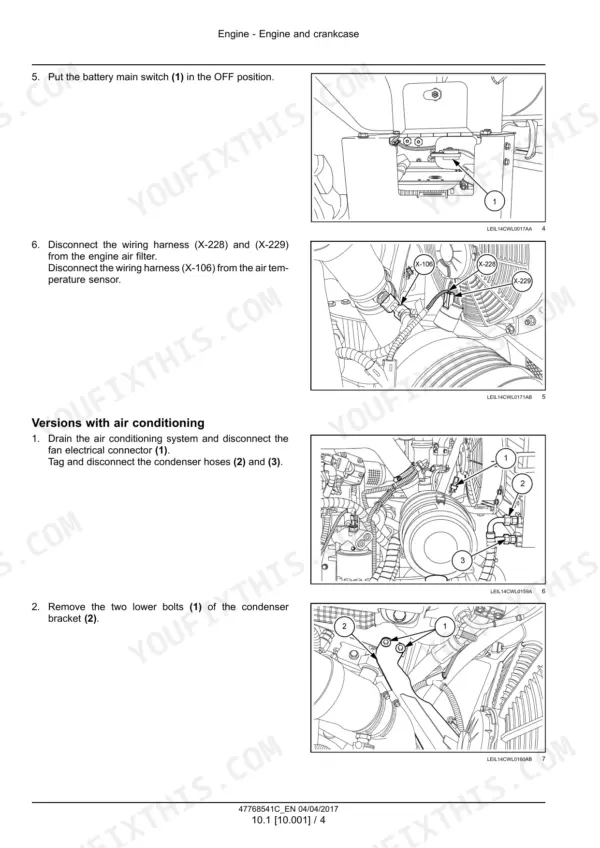
Part of the New Holland Repair Manuals.
Strip, set and rebuild the New Holland W50C, W60C, W70C and W80C Stage IIIB compact wheel loaders with this factory service manual. It is part number 47768541C, in English, dated March 2017. It covers all eight variants: the W50C and W60C in TC and ZB form, and the W70C and W80C in standard and High Speed.
Guessing gets expensive on these loaders. Fill a High Speed gearbox to the standard 1.3 L mark and you have overfilled it. The book gives you the inching valve pressures, steering relief settings, A/C charge and engine mount torque.
The teardown chapters come with hydraulic and electrical schematics, a DTC index and a special tool index. The rear axle chapter covers the TB 172 and the TB 138.5 High Speed transmissions separately.
What's Inside This New Holland W50C, W60C, W70C, W80C Manual
| System | Pages | Key Topics |
|---|---|---|
| Introduction and Specifications | 1-51 | Applicability, Safety Rules, Machine Identification, Capacities and Specifications, Consumables, Tightening Precautions |
| Engine | 52-87 | Engine Removal and Installation, Engine Mounts, Emission Sensors, Fuel Tank Removal and Installation |
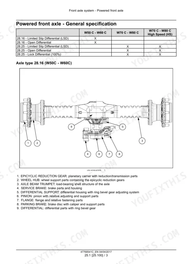
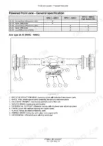
| Drive Shaft and Front Axle | 88-213 | Drive Shaft Service, Powered Front Axle, Differential Support, Bevel Gears, Pinion Adjustment, Wheel Hubs, Brake-Equipped Hubs, Troubleshooting |
| Rear Axle and Transmission | 214-367 | Rear Axle Dimensions, TB 172 Transmission, TB 138.5 High Speed Transmission, Differential, Bevel Pinion, Planetary Reduction Gears, Wheel Hubs and Axle Shafts, Troubleshooting |
| Hydrostatic Drive | 368-381 | Inching Valve and Creep Speed Valve Specifications, Removal and Installation |
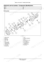
| Brakes and Controls | 382-439 | Hydraulic Service Brakes, Brake Master Cylinder, Brake Calipers, Parking Brake Cable and Checks, Front Axle Brake Bleeding |
| Hydraulic Systems | 440-477 | Hydraulic Schematic Frames 01 and 02, Travel System Troubleshooting, Oil Reservoir Removal and Installation |
| Hydraulic Pumps | 478-521 | Gear Pump and Tandem Gear Pump, Variable Displacement Pump, High Pressure Valves, Pump Hydraulic Schema, Rotary Assembly Service, Pump Adjustment |
| Main Control Valve and Hand Controls | 522-587 | Main Control Valve, Pilot Control Manifold, Flow Diverter Valve, High Flow Valve and Quick Couplings, Hydraulic Hand Control |
| Hydraulic Travel System | 588-621 | Gear Shift Valve, Travel Motor Specifications and Operation, Motor Checks, Removal, Disassembly and Assembly |
| Loader Arm and Bucket Hydraulics | 622-719 | Lift Arm and Bucket Control Cylinders, Seals and Bushings, Ride Control, Anti-Drop Valves, Quick Couplers, Bucket Hydraulics Troubleshooting |
| Frames and Ballasting | 720-741 | Upper and Lower Articulation Joints, Frame Pivot Service, Counterweight and Additional Counterweight |
| Steering | 742-779 | Hydrostatic Steering, Relief and Shock Valves, Load Sensing, Priority Valve, Steering Control Valve and Cylinder Service |
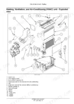
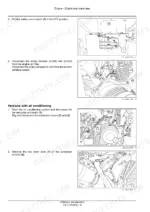
| Cab Climate Control | 780-815 | HVAC Unit, Refrigerant and Oil Capacities, A/C Operation, Leak Testing, Discharging and Charging, Compressor and Condenser, Troubleshooting |
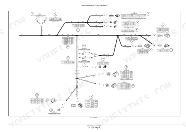
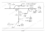
| Electrical Harness Drawings | 816-901 | Main Cab, Cab Roof, Frame, Engine and Transmission Harness Drawings, Lighting Circuits, Battery and Ground Cables, Auxiliary Electrical Options |
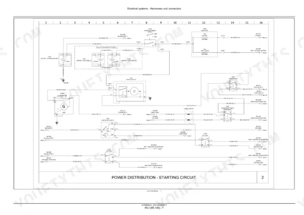
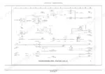
| Electrical Schematic Sheets | 902-977 | Connector Identification, Power Distribution and Starting, UCM Fuses, Functional Circuit Schematics, CAN Bus Diagnostics, Voltage Sources, Fuse and Relay Service |
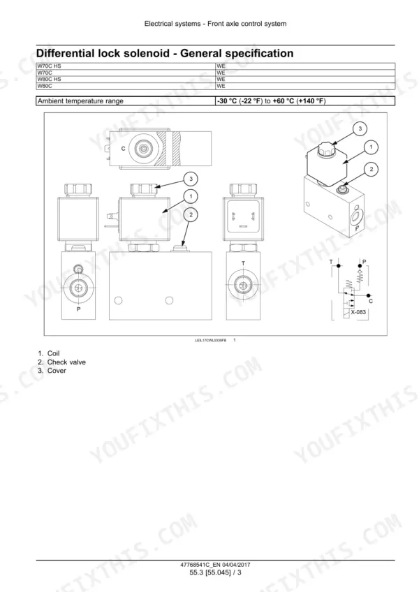
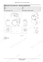
| Differential Lock and Heater Blower Electrics | 978-989 | Differential Lock Solenoid and Valve, Heater Blower Removal and Installation |
| Instruments and Warning Indicators | 990-999 | UCM and ECU Architecture, ADIC Instrument Cluster, Diagnostic Connector, Fault Code Ranges, Fault Reset Procedure, Indicator Lamps |
| Fault Codes (DTC) | 1000-1557 | Driveline Solenoid, Engine Sensor, Fuel Injection, ECU Supply, Electrohydraulic Control, Brake and Vehicle Control, CAN Communication and Instrument Cluster Fault Codes, Fault Code Index |
| Front Loader and Bucket | 1558-1589 | Z-Bar and TC/XT Loader Arm Removal and Installation, Horizontal Pin and SSL Quick Coupler Service |
| Platform, Cab and Bodywork | 1590-1611 | Cab Removal, Installation and Lifting, Cab Mounts, Hydraulic and Electrical Connections |
| Special Tool Index | 1612-1617 | Differential, Pinion, Wheel Hub, Transmission, Axle Shaft, Brake, Articulation and a/C Service Tools |
Quick Reference Specifications
| Specification | Value | Page |
|---|---|---|
| Engine oil capacity (with filter change) | 7.0 L (7.4 US qt) | p. 39 |
| Cooling system total capacity (50% coolant - 50% water) | 13 L (3.4 US gal) | p. 39 |
| Fuel system capacity | 86.0 L (22.7 US gal) | p. 39 |
| Hydraulic system and transmission total capacity | 53 L (14 US gal) | p. 39 |
| Hydraulic reservoir capacity | 40.0 L (10.6 US gal) | p. 39 |
| Front axle differential oil, W50C-W60C | 7.5 L (2.0 US gal) | p. 39 |
| Front axle differential oil, W70C-W80C (incl. High Speed) | 8.0 L (2.1 US gal) | p. 40 |
| Axle reduction gear oil (each side), W50C-W60C | 0.7 L (0.2 US gal) | p. 39 |
| Gearbox oil, W50C-W60C and W70C-W80C standard | 1.3 L (0.3 US gal) | p. 40 |
| Gearbox oil, W70C-W80C High Speed | 0.75 L (0.2 US gal) | p. 41 |
| Brake system service capacity | 1.0 L (1.1 US qt) | p. 39 |
| A/C refrigerant charge (R134A) | 1.4 kg (3.1 lb) | p. 798 |
| Inching valve setting, W50C-W60C | 30 bar (435 psi) | p. 372 |
| Inching valve setting, W70C-W80C | 24 bar (348 psi) | p. 372 |
| Main control valve nominal flow, W50C-W60C | 65 L/min (17.2 US gpm) | p. 524 |
| Main control valve nominal flow, W70C-W80C | 85 L/min (22.5 US gpm) | p. 526 |
| Steering relief valve setting | 175 bar (2538 psi) | p. 746 |
| Steering shock valve setting | 240 bar (3480 psi) | p. 746 |
| Engine mounting bolts torque | 244 - 298 N·m (180 - 220 lb ft) | p. 69 |
| A/C oil charge (PAG SP20) | 197 ml (6.67 US fl oz) | p. 798 |