

![New Holland E235SR E235BSR Repair Manual [Excavator]](https://youfixthis.com/wp-content/uploads/2012/02/Manual_Download-300x300.jpg)
Part of the New Holland Parts Manuals.
A factory service manual for the New Holland E50BSR compact crawler excavator, Tier 4, publication 87481006, issued 01/2008, 1,021 pages, applicable to machines from serial PJ06-08001 onward.
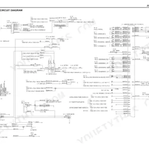
The hydraulic section prints each operation as its own colour circuit sheet. Page 131 is typical: travel forward at 2nd speed, with the oil path traced in colour through the variable displacement pump, the 11-spool control valve, the travel motors with their counterbalance and brake valves and the swivel joint, plus a numbered component key and the relief pressure table printed on the sheet. Matching sheets cover slew, bucket, boom, arm, swing, dozer, the nibbler and breaker circuit and the combined travel/dozer and travel/boom operations. The electric circuit diagram runs across three sheets starting on page 158: fuse box, battery relay, key switch with its terminal position table, safety relay, engine stop relay and solenoid, starter motor, generator, air heater, 45 A fusible link, wiper, heater and radio, with gauge and colour carried on every wire code.
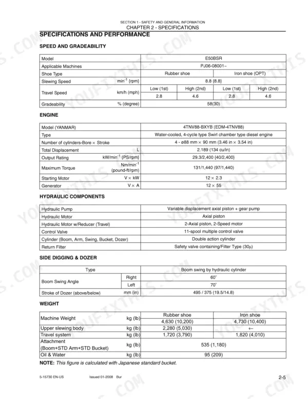
Just under 400 pages at the back are a complete Yanmar TNV service manual bound in, covering the whole TNV family rather than only the 4TNV88-BXYB fitted to this machine. The specs a buyer checks are here: Yanmar 4TNV88-BXYB rated 29.3 kW at 2400 min-1 (40 PS / 2,400 rpm), machine weight 4,630 kg (10,200 lb) with rubber shoes, main relief valves P1,P2 at 22.5 MPa {3263 psi} and P3 at 21.2 MPa {3074 psi}.
What's Inside This New Holland E50BSR Manual
| System | Pages | Key Topics |
|---|---|---|
| Front Matter & Master Table of Contents | 1-15 | Book/Form Numbers for Every Chapter, General Safety Information, Section Index |
| General Precautions for Making Repairs | 16-25 | Preparation Before Disassembling, International Unit System, Quantities and Conversion |
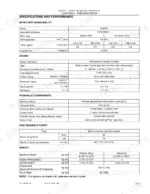
| Specifications & Performance | 26-39 | Speed and Gradeability, Machine and Components Weight (Dry), Machine Dimensions, Type of Crawler Shoes, Engine Performance Curve, Transportation and Loading on a Trailer |
| Attachment Dimensions | 40-67 | Boom, Arm and Bucket Dimensions, Working Range, Bucket Options |
| Tools & Standard Maintenance Time Table | 68-95 | Tightening Torques for Capscrews and Nuts, Tightening Torque for Hose and Fitting, Sleeve Type Tube Fittings, Counterweight Lifting Jig, Upper Frame Lifting Jig, Standard Job Times |
| Maintenance Standards & Test Procedures | 96-121 | Performance Inspection Standard Table, Measuring Engine Speed, Measuring Hydraulic Oil Pressure, Measuring Travel Performances, Measuring Slew Performances, Measuring Slew Bearing Performances |
| Hydraulic System - Colour Operating Circuits | 122-151 | Function and Features of the Hydraulic Circuit, Hydraulic Circuits and Component Models, Travel, Slew, Bucket, Boom, Arm and Dozer Circuits, Nibbler and Breaker Circuit, Travel/Dozer and Travel/Boom Combined Operation, Relief Valve Settings Printed on the Circuit |
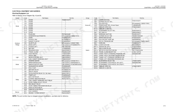
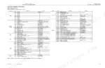
| Electrical System - Circuit Diagrams & Harness | 152-207 | Electric Circuit Diagram, Sheets 1/3 to 3/3, How to Read the Circuit Diagram and Harness Connection, Electrical Equipment List with Part Numbers, Drawings for Components and Harness Routing, Canopy and Cab Harness Differences |
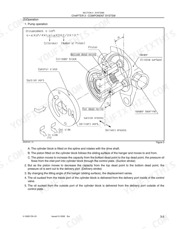
| Component System - Hydraulic Components in Detail | 208-287 | Hydraulic Pump, Control Valve, Pilot Valve (Attachment), Pilot Valve (Travel), Swivel Joint, Cylinders |
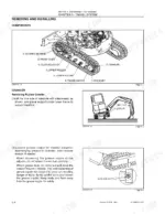
| Disassembly & Assembly - Attachments | 288-323 | Removing and Installing the Bucket, Cylinder Disassembly and Assembly, Setting Tools, Attachment Maintenance Standards |
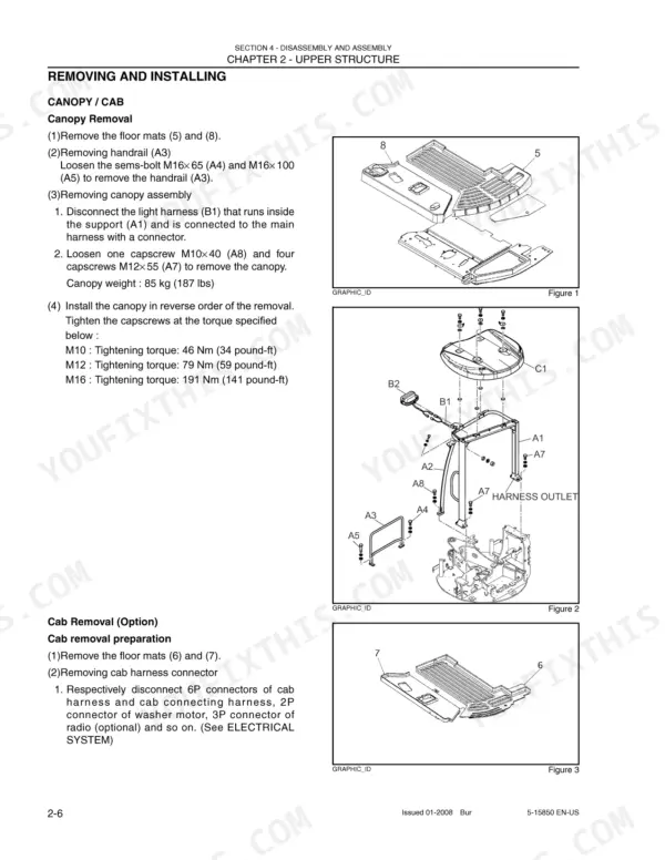
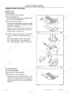
| Disassembly & Assembly - Upper Structure | 324-483 | Canopy / Cab Removal, Counterweight, Floor Plate Assembly, Multi-Control Valve, Solenoid Valve, Fuel Tank and Hydraulic Oil Tank |
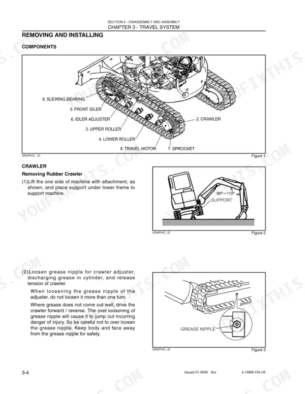
| Disassembly & Assembly - Travel System & Undercarriage | 484-577 | Upper Roller, Lower Roller Assembly, Front Idler and Idler Adjuster, Track and Holding-Down Nut, Travel Motor and Reducer |
| Troubleshooting - Hydraulic, Electrical & Engine | 578-623 | Troubleshooting the Hydraulic System, Attachment Operation Faults, General Precautions Before Fault-Finding, Engine Fault Charts |
| Yanmar TNV Service Manual - Preface, Warranties & Safety | 624-668 | New Holland Preface Pointing to the Attached Yanmar Manual, Yanmar Limited Warranty, Emission System Warranty, Usa, 97/68/EC Certified Engines |
| Yanmar TNV - General Service Information & Periodic Maintenance | 669-760 | Component Identification Across the TNV Range, Location of Labels and Emission Control Labels, Function of Major Engine Components, Function of Cooling System Components, Diesel Fuel Requirements, Periodic Maintenance Schedule |
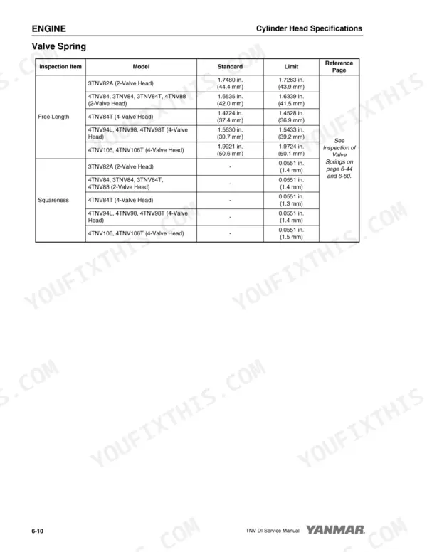
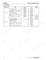
| Yanmar TNV - Engine Disassembly, Inspection & Reassembly | 761-868 | Cylinder Head Specifications, Cylinder Block Specifications, Special Torque Chart, Special Service Tools and Measuring Instruments, 2-Valve and 4-Valve Cylinder Heads, Measuring and Adjusting Valve Clearance |
| Yanmar TNV - Fuel System, Cooling System & Lubrication | 869-946 | Fuel System Diagram, Fuel Injection Pump, Fuel System Specifications, Cooling System Diagram, Lubrication System Components |
| Yanmar TNV - Turbocharger, Starter Motor & Alternator | 947-1004 | Turbocharger Components and Functions, Washing Procedure and Periodic Inspection, Starter Motor Specifications, Starter Motor Components, Alternator Wiring Diagram, Dynamo Wiring Diagram |
| Yanmar TNV - Troubleshooting & Electrical Wiring | 1005-1021 | Troubleshooting by Symptom, Measuring Compression, Representative Engine Wiring Diagram |
Quick Reference Specifications
| Specification | Value | Page |
|---|---|---|
| Engine | ||
| Engine | Yanmar 4TNV88-BXYB (EDM-4TNV88), water-cooled 4-cycle swirl chamber diesel | p. 31 |
| Output rating | 29.3 kW at 2400 min-1 (40 PS / 2,400 rpm) | p. 31 |
| Maximum torque | 131 Nm at 1,440 min-1 (97 lb-ft / 1,440 rpm) | p. 31 |
| Machine | ||
| Machine weight, rubber shoes | 4,630 kg (10,200 lb) | p. 31 |
| Machine weight, iron shoes | 4,730 kg (10,400 lb) | p. 31 |
| Gradeability | 58% (30 degrees) | p. 31 |
| Travel system | ||
| Travel speed | low (1st) 2.8, high (2nd) 4.6 km/h | p. 31 |
| Slew | ||
| Slewing speed | 8.8 min-1 | p. 31 |
| Slew relief valve | 18.5 MPa {2680 psi} | p. 131 |
| Hydraulic system | ||
| Control valve | 11-spool multiple control valve | p. 31 |
| Main relief valve P1, P2 | 22.5 MPa {3263 psi} | p. 131 |
| Main relief valve P3 | 21.2 MPa {3074 psi} | p. 131 |
| Overload relief valves | 27.5 MPa {4000 psi} and 25.5 MPa {3700 psi} | p. 131 |
| Electrical system | ||
| Starting motor / generator | 12 V x 2.3 kW / 12 V x 55 A | p. 31 |
| Pilot circuit | ||
| Pilot relief valve | 3.5 MPa {508 psi} | p. 131 |
New Holland E50BSR Common Problems This Manual Covers
The whole machine feels weak, the boom and arm move slowly and stall under load.
Warm the machine up and measure hydraulic oil pressure following the performance inspection standard table. Compare readings against the settings printed on the circuit sheets: main relief valve P1,P2 22.5 MPa {3263 psi} and main relief valve P3 21.2 MPa {3074 psi}. Low or unstable readings separate relief valve trouble from pump trouble.
Manual Section: Maintenance Standards & Test Procedures p. 96The machine pulls to one side when travelling, or one track is noticeably slower than the other.
Trace the travel circuit on the colour operating sheet, page 131 shows travel forward at 2nd speed, following the oil from the variable displacement pump through the 11-spool control valve and the swivel joint to each travel motor's counterbalance and brake valves. Run the measuring travel performances check and compare the two sides; rated travel speed is low (1st) 2.8 and high (2nd) 4.6 km/h. A difference between sides isolates the fault to one valve section, the swivel joint or one travel motor.
Manual Section: Hydraulic System - Colour Operating Circuits p. 131Turn the key and nothing happens, no crank, or it cranks but will not start.
Work through sheet 1/3 of the electric circuit diagram on page 158 in order: battery relay, key switch and its terminal position table, safety relay, engine stop relay and solenoid, then the starter motor, rated 12 V x 2.3 kW. Wire codes on the diagram carry gauge and colour for continuity checks. If it cranks but will not fire, the Yanmar section picks it up with troubleshooting by symptom and measuring compression.
Manual Section: Electrical System - Circuit Diagrams & Harness p. 152Slew is weak, drifts under load, or is noisy when starting and stopping a swing.
Check slew relief valve pressure against the 18.5 MPa {2680 psi} setting printed on the hydraulic circuit sheet, then run the measuring slew performances and measuring slew bearing performances checks; rated slewing speed is 8.8 min-1. With those numbers in hand, the hydraulic system troubleshooting charts separate relief valve, slew motor and slew bearing causes.
Manual Section: Troubleshooting - Hydraulic, Electrical & Engine p. 578Frequently Asked Questions
Will this manual match my E50BSR?
It covers the New Holland E50BSR compact crawler excavator, Tier 4, from serial PJ06-08001 onward. The book is publication 87481006, issued 01/2008. Check the serial number on your machine against that range before you buy.
Does it give real pressure settings for the hydraulics?
Yes, they are printed on the hydraulic circuit sheets: main relief valve P1,P2 22.5 MPa {3263 psi}, main relief valve P3 21.2 MPa {3074 psi}, overload relief valves 27.5 MPa {4000 psi} and 25.5 MPa {3700 psi}, slew relief valve 18.5 MPa {2680 psi}, pilot relief valve 3.5 MPa {508 psi}. The Maintenance Standards & Test Procedures section shows how to measure hydraulic oil pressure so you can compare your machine against those values. p. 131
What is the Yanmar section at the back, and is it the right engine?
Pages 624-1021, just under 400 pages, are a complete Yanmar TNV series service manual bound in behind a one-page New Holland preface. It covers the whole TNV family, not only the 4TNV88-BXYB fitted to this machine, with cylinder head and cylinder block specifications, a special torque chart, valve clearance adjustment, the fuel injection pump, cooling and lubrication systems, turbocharger, starter motor, alternator and troubleshooting by symptom. That bound-in engine book is why the page count is as high as it is. p. 947
Are there proper wiring diagrams for chasing an electrical fault?
Yes. The electric circuit diagram runs across three sheets, starting at page 158 with the instrument panel, relay console and engine side: fuse box, battery relay, key switch with its terminal position table, safety relay, engine stop relay and solenoid, starter motor, generator and air heater. Wire codes carry gauge and colour. The same section explains how to read the circuit diagram and harness connection, lists the electrical equipment with part numbers, and includes harness routing drawings with canopy and cab differences. p. 158
Is this a scan, and can I search it?
It is a scan of the printed book with a text recognition layer added, so it is searchable and you can jump to sections by keyword. Treat search as a navigator: for part numbers and other alphanumeric codes, read the value off the page image itself rather than trusting copied text.






Reviews
There are no reviews yet.