Part of the New Holland Repair Manuals.
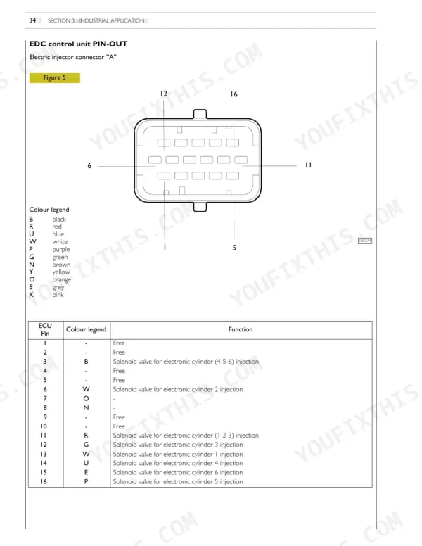
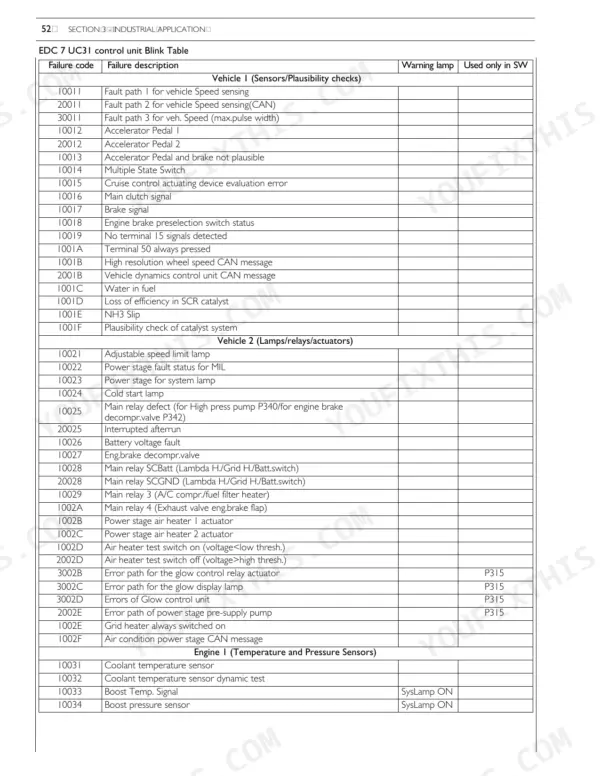
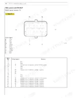
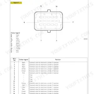
The EDC 7 UC31 control unit is where these engines usually stall a rebuild: a blink code, a sensor fault, and no clear line between wiring, sensor, or pump-injector. Electrical Equipment gives the pin-out diagrams and engine sensor data, and Troubleshooting carries the blink code table and failure descriptions that turn a flashing lamp into a named fault.
The rest of the book is the strip-down. Mechanical Components takes the F3BE0684H and F3BE0684G apart and back together, flywheel to camshaft to rocker-arm shaft, while Overhaul and Technical Specifications holds the cylinder block, liner and crankshaft figures. Fuel, cooling and maintenance planning fill in around them. 154 pages, English, PDF download, publication 87523643.
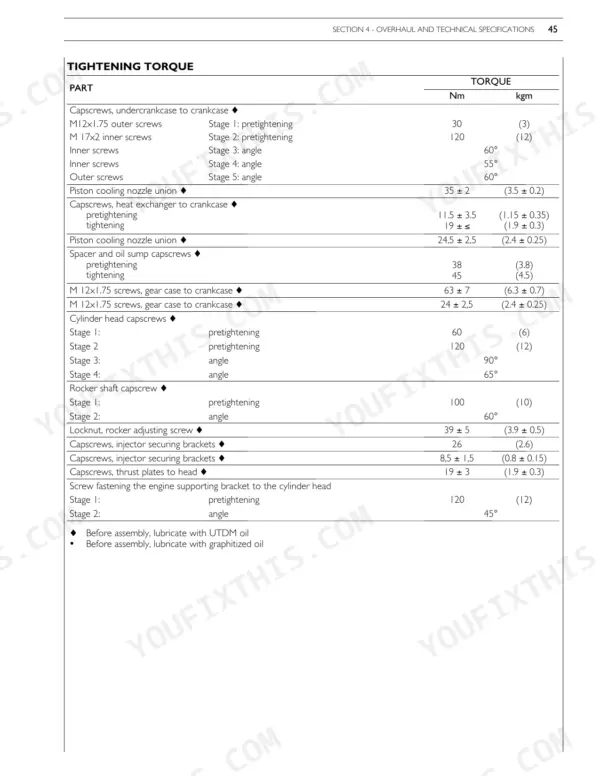
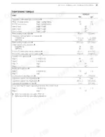
Every week an engine sits half apart is a week of lost work, so the numbers are here: clearances, wear limits and the staged torque sequences, plus the tool numbers to quote when you order.
What's Inside This Repair Manual
| System | Pages | Key Topics |
|---|---|---|
| General Specifications | 5-18 | Cooling (Water Pump, Thermostat), Turbocharging |
| Fuel | 19-24 | Feeding, Fuel Supply Diagram, Injector Pump |
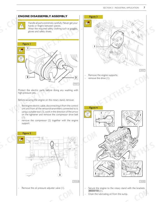
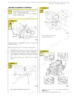
| Mechanical Components - Disassembly and Assembly | 25-37 | Engine Disassembly, Engine Assembly, Flywheel, Camshaft, Pump-Injectors, Rocker-Arm Shaft |
| Electrical Equipment | 38-52 | EDC 7 UC31 Control Unit, Pin-Out Diagrams, Engine Sensors, Alternator, Starting Motor |
| EDC System Functions | 53-72 | Fuel Dosing, Delivery Correction, Injection Lead Control, Engine Start, Cold Start, After Run |
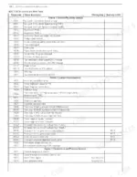
| Troubleshooting | 73-84 | Blink Code Table, Failure Descriptions, Sensor Faults, Actuator Faults, CAN-Bus Interfaces |
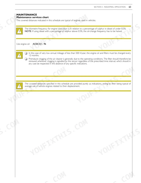
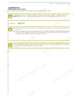
| Maintenance Planning | 85-90 | Maintenance Services Chart, Maintenance Intervals, Off-Plane Operations |
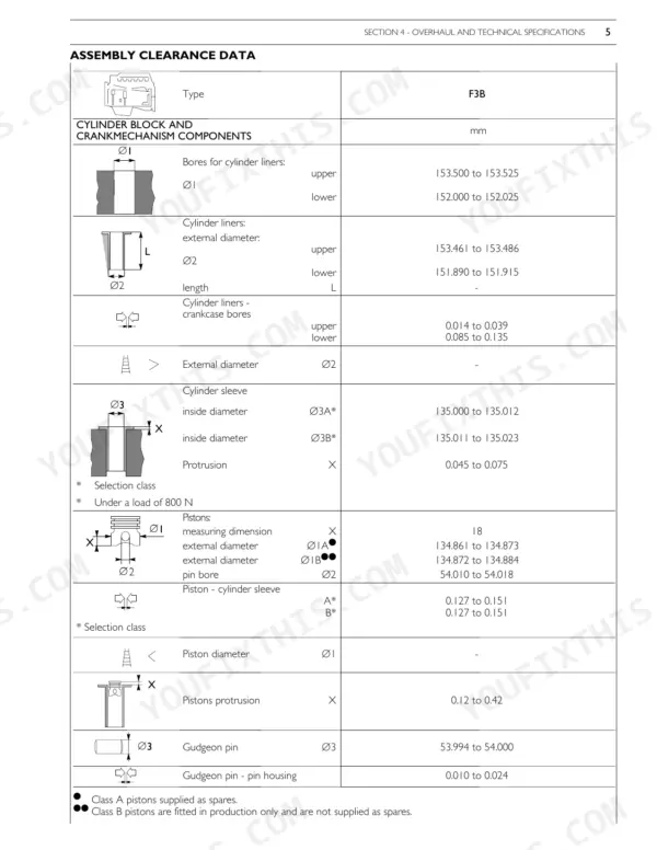
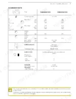
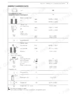
| Overhaul and Technical Specifications | 91-138 | Cylinder Block, Cylinder Liners, Crankshaft |
| Tools | 139-150 | Tools List |
| Safety Prescriptions | 151-154 | Standard Safety Prescriptions |
Quick Reference Specifications
| Specification | Value | Page |
|---|---|---|
| All Models | ||
| Cylinder head capscrews | Stage 1: 60 Nm, Stage 2: 120 Nm, Stage 3: 90°, Stage 4: 65° | p. 135 |
| Engine flywheel screw tightening torque | First phase: 120 Nm, Second and third phase: 60° + 30° | p. 39 |
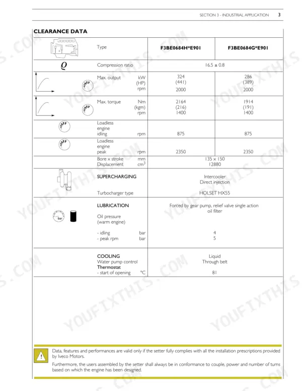
| Bore | 135 mm | p. 93 |
| Cylinder head screw tightening torque | 1st phase: 60 Nm, 2nd phase: 120 Nm, 3rd phase: 120°, 4th phase: 60° | p. 37 |
| Adjusting screw locking nut torque | 5 Nm (0.5 kgm) | p. 45 |
| Rocker shaft capscrew | Stage 1: 100 Nm, Stage 2: 60° | p. 135 |
| Bore x stroke | 135 x 150 mm | p. 27 |
| Displacement | 12880 cm3 | p. 27 |
| F3BE0684H*E901 | ||
| Max. output (F3BE0684H*E901) | 324 kW (441 HP) at 2000 rpm | p. 27 |
| Max. torque (F3BE0684H*E901) | 2164 Nm (216 kgm) at 1400 rpm | p. 27 |
| F3BE0684G*E901 | ||
| Max. output (F3BE0684G*E901) | 286 kW (389 HP) at 2000 rpm | p. 27 |
| Max. torque (F3BE0684G*E901) | 1914 Nm (191 kgm) at 1400 rpm | p. 27 |