
Part of the New Holland Repair Manuals.
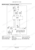
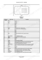
Bottom end work is where this book earns its price: the New Holland F3BFE series service manual PDF, OEM ID 84473721, gives its longest chapter to connecting rods, pistons, crankshaft, main bearings, and crankpins, then fills the rest of its 252 pages with cylinder head, valve train, fuel injection, turbocharger, cooling, lubrication, and starting systems across eight F3BFE613 variants. Wiring diagrams trace the harness into the electronic control module, and factory torque tables back you up on every fastener in the block. Procedures run from valve lash adjustment through crankshaft endplay checks, each one ending in a number you can measure against. When your injectors come out, pop test them against the 290 to 302 bar calibration range, and expect 3 bar of oil pressure at warm idle once it fires. A bottom end built on guessed clearances never sleeps easy. Pay once and this bookmarked, keyword searchable file is yours for as long as the engine runs.
What's Inside This New Holland F3BFE Series Manual
| System | Pages | Key Topics |
|---|---|---|
| Service Manual | 1 | Ecology and Environment, Safety Rules, Equipment Servicing, Shop and Assembly, Tightening Torques |
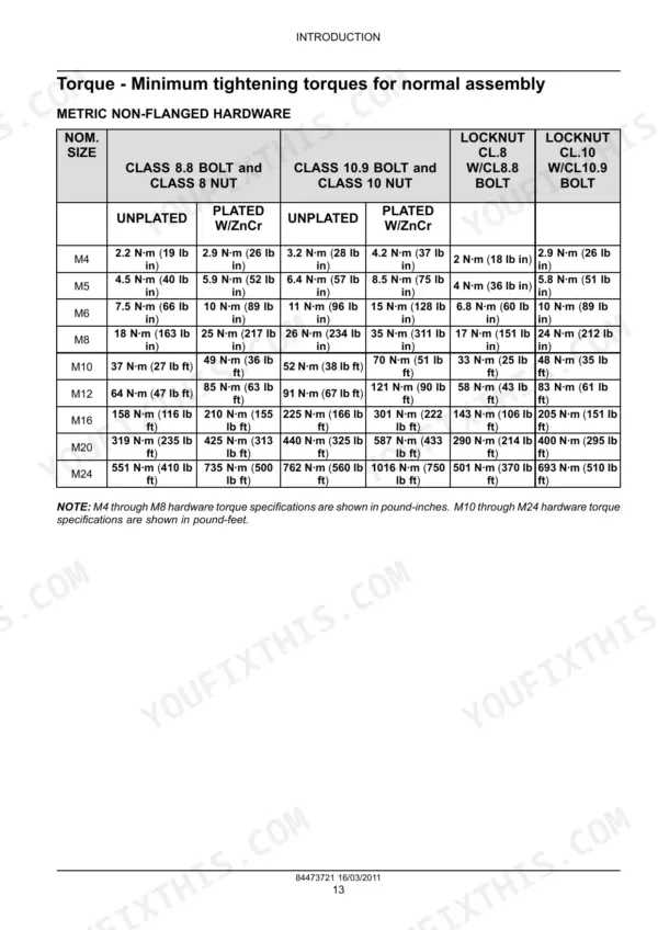
| Introduction | 3-20 | Ecology and the Environment, Safety Rules, Equipment Servicing, How to Use and Navigate This Manual, Shop and Assembly, Torque Specifications |
| Electrical Power System | 21-26 | Alternator Overview, Alternator Removal, Alternator Installation |
| Engine Overview and Specifications | 27-37 | Engine Overview, Service Limits, Engine Views, Firing Order |
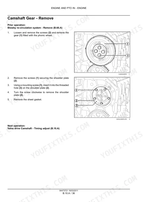
| Valve Drive and Timing Gear | 38-42 | Rocker Assembly, Rocker Shaft, Timing Gear Overview, Idler Gear, Twin Idler Gear |
| Connecting Rod, Piston, and Crankshaft | 43-110 | Connecting Rod and Piston, Crankshaft, Main Bearings, Crankpins, Piston Rings, Piston Pin |
| Cylinder Head and Valve Train | 111-152 | Cylinder Head Removal and Installation, Valve Guide, Valve Seat, Injector Cup, Valve Cover |
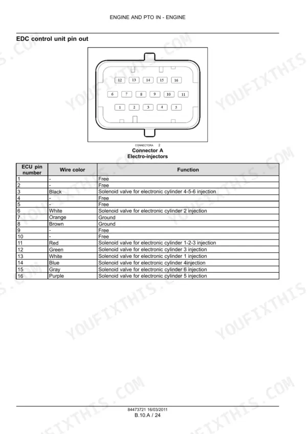
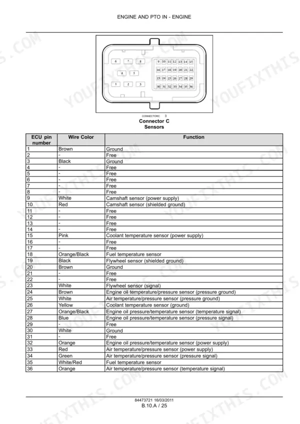
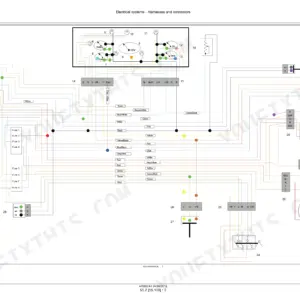
| Electronic Control and Wiring | 153-158 | Wiring Harness, Electronic Control Module, Control Module Removal and Installation |
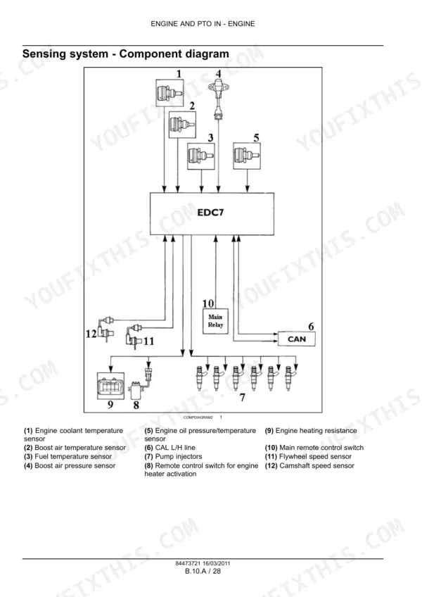
| Fuel and Injection System | 159-176 | Fuel Injection System, Regulator Valve, Fuel Injector, Fuel Transfer Pump, Temperature Sensor, Air Temperature-Pressure Sensor |
| Air Intake System | 177-184 | Turbocharger, Air Intake Manifold, Turbocharger Installation, Turbocharger Removal, Air Intake Manifold Installation, Air Intake Manifold Removal |
| Exhaust System | 185-190 | Exhaust Manifold, Exhaust Manifold Removal, Exhaust Manifold Installation |
| Engine Coolant System | 191-212 | Thermostat, Water Pump, Coolant Line, Belt Tensioner, Idler Pulley, Coolant Temperature Sensor |
| Lubrication System | 213-240 | Oil Pump, Oil Filter, Oil Pressure Regulator Valve, Oil Cooler, Oil Pan, Spray Nozzle |
| Starting System | 241-248 | Grid Heater, Engine Starter, Engine Starter Removal, Engine Starter Installation |
Quick Reference Specifications
| Specification | Value | Page |
|---|---|---|
| Injector calibration | 290 - 302 bar (4205 - 4379 psi) | p. 31 |
| Injector protrusion | 0.53 - 1.34 mm (0.021 - 0.053 in) | p. 33 |
| Oil Pressure (Warm engine) - Idling | 3 bar (43.5 psi) | p. 31 |
| Oil Pressure (Warm engine) - Peak RPM | 4.5 bar (65.3 psi) | p. 31 |
| Thermostat (Start of opening) | 81 °C (177.8 °F) | p. 31 |
| Pre-post heating activation temperature | below 10 °C (50 °F) | p. 47 |
| Turbocharger fastening screws torque | 75 Nm (55.3 lb ft) | p. 180 |
| Turbocharger nuts torque | 45 Nm (33.2 lb ft) | p. 180 |
| Coolant temperature sensor voltage range at 60 - 90 °C (140 - 194 °F) | 0.6 - 2.4 V | p. 197 |
| Bore | 135 mm | p. 31 |
| Stroke | 150 mm | p. 31 |
| Displacement | 12880 cm³ | p. 31 |
New Holland F3BFE Series Common Problems This Manual Covers
New Holland F3BFE613 diesel hard starts below freezing, cranks strong but no fire
Check battery voltage at the starter first; this is a 24 V system with a 7.8 kW starter per page 244. Verify the grid heater relay pulls in; pre-post heating activates below 10 °C (50 °F) per page 47. Test heater element continuity, then follow the grid heater procedures starting on page 241.
Manual Section: Starting System p. 241Engine loses power under load, white smoke and rough idle after fuel filter change
Bleed air from the fuel system first; trapped air after a filter change mimics injector failure. Check the transfer pump and screens per the procedures starting on page 159. Pop test suspect injectors; opening pressure must read 290 to 302 bar (4205 to 4379 psi). Torque injector brackets to 26 Nm (19.2 lb ft) per page 173.
Manual Section: Fuel and Injection System p. 159Coolant temperature climbs to derate at full load in warm weather
Test the thermostat in heated water; it must start opening at 81 °C (177.8 °F) per page 31. Back probe the coolant temperature sensor and expect 0.6 to 2.4 V between 60 and 90 °C per page 197. Clean the cooling pack, then inspect the water pump and belt tensioner using the procedures starting on page 191.
Manual Section: Engine Coolant System p. 191Low oil pressure warning at hot idle, gauge needle fluctuates
Verify with a mechanical gauge before condemning the pump; a warm engine should hold 3 bar (43.5 psi) at idle and 4.5 bar (65.3 psi) at peak RPM per page 31. If readings run low, replace the oil filter, then inspect the oil pump and pressure regulator valve per the lubrication procedures starting on page 213.
Manual Section: Lubrication System p. 213Sluggish acceleration with black smoke under load, whistling noise near the turbocharger at speed
Inspect boost hoses and clamps for splits and oil residue, then pressure test the charge circuit. Check the turbocharger shaft for play using the air intake procedures starting on page 177. On reinstall, torque the turbocharger fastening screws to 75 Nm (55.3 lb ft) and the nuts to 45 Nm (33.2 lb ft) per page 180.
Manual Section: Air Intake System p. 177Loud tappet clatter from the valve cover, idle stays rough after cylinder head reassembly
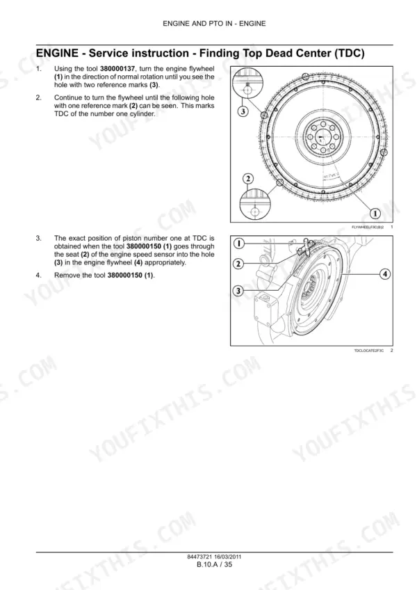
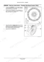
Set valve lash cold; intake is 0.4 mm and exhaust is 0.6 mm per page 31. Find Top Dead Center using the engine procedures starting on page 27, then work through each rocker in firing order following the rocker assembly adjustment steps beginning on page 38. Recheck lash after the locknuts are tight.
Manual Section: Valve Drive and Rocker Assembly p. 38Frequently Asked Questions
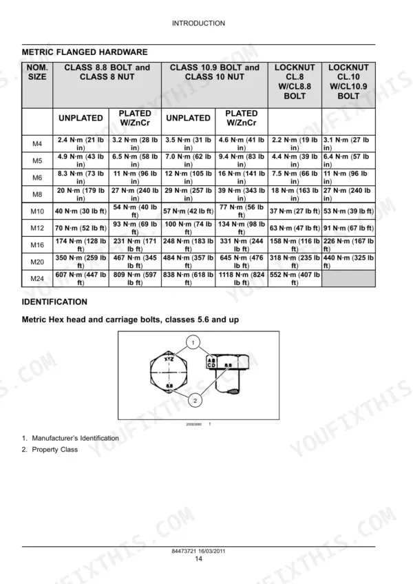
What is the torque for M10 non-flanged bolts on the New Holland F3BFE613 engine?
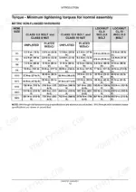
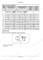
For M10 non-flanged hardware, the torque specification for a Class 8.8 bolt and Class 8 nut is 37 N·m (27 lb ft) for unplated, and 49 N·m (36 lb ft) for plated with ZnCr. p. 15
What are the intake and exhaust valve lash settings on the New Holland F3BFE613 engine?
The valve lash setting for the intake valves is 0.4 mm (0.016 in) and for the exhaust valves is 0.6 mm (0.024 in) when the engine is cold. p. 31
How are the under block inner screws tightened on the New Holland F3BFE613 engine?
The inner screws must be tightened to 120 Nm (89 lb ft), then turned an additional 60 degrees, and finally an additional 55 degrees using tool 380001001. p. 133
What is the oil pressure regulator valve opening pressure on the New Holland F3BFE613 engine?
The oil pressure control valve is located on the left hand side of the crankcase and has a start of opening pressure of 5 bar (72.5 psi). p. 220
What is the oil filter tightening torque on the New Holland F3BFE613 engine?
When mounting the oil filters, they should be tightened to a torque of 35 - 40 Nm (25.8 - 29.5 lb ft). p. 218
What format is this New Holland F3BFE Series manual in?
You get a 252-page searchable PDF that downloads instantly after checkout. Open it on your laptop, tablet, or phone, and bring it right to the shop floor.
Am I able to print pages from this New Holland F3BFE Series manual?
Printing is allowed without restriction. Pull the pages you need for the job and bin them when they get greasy.






Reviews
There are no reviews yet.