
Part of the New Holland Repair Manuals.
The hydrostatic drive is where a Guardian SP310F tests a mechanic. It covers planetary hubs and the sun gear, park and service brake tests, and pump, motor and joystick calibration. This New Holland service manual 48142770 walks you through all of it for PIN YHF001227 and above.
It also covers the FPT NEF 6.7L engine with its SCR and DEF lines, axle legs and kingpins, and steering calibration. You also get cab climate control, the Hypro product pumps, fault codes with cause and solution, and fold-out electrical and hydraulic schematics.
What's Inside This New Holland Guardian SP310F Manual
| System | Pages | Key Topics |
|---|---|---|
| Introduction, Safety and General Specification | 1-34 | Contents, Safety Rules, Fluids and Capacities, Tires, General Specification, Pressures, Product Identification |
| Engine | 35-112 | Engine Removal and Installation, Oil and Filter, Fuel Tank, Air Cleaner, SCR and DOC, DEF Lines, Radiator, Deaeration Tank |
| Front Axle System | 113-126 | Front Wheel Leg Removal, Kingpin Assembly, Leg Installation, Sleeve Bushings |
| Rear Axle System | 127-140 | Rear Leg Removal, Suspension Cylinder, Leg Installation, Sleeve Bushing |
| Hydrostatic Drive | 141-196 | Planetary Drive and Hub, Park and Service Brake Tests, Roll and Leak Test, Sun Gear, Towing, Pump Calibration |
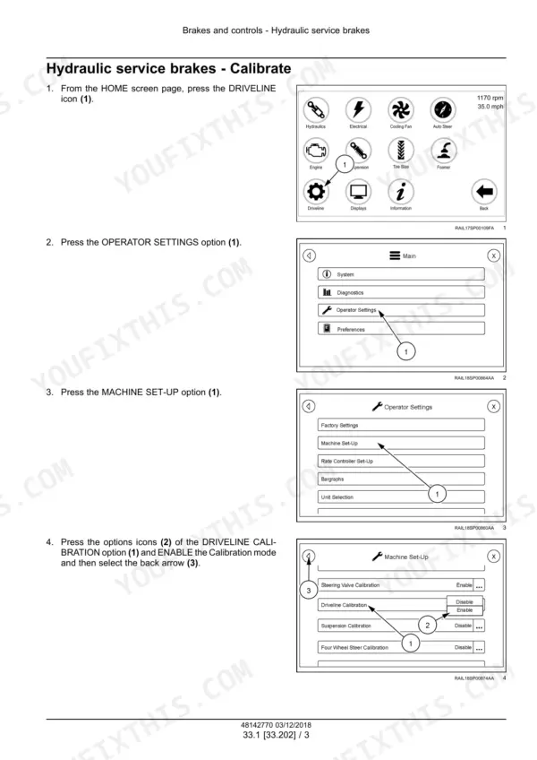
| Brakes and Controls | 197-212 | Service Brake Calibration, Brake Pedals, Pressure Accumulator |
| Hydraulic Systems | 213-352 | High Flow Hydraulics, Pressure Settings, Hydraulic Schematic Frames, Accumulator Charging, Reservoir and Cooler, Auxiliary Pump, Fan Drive, Boom and Suspension Cylinders |
| Pneumatic System | 353-364 | Air Tank, Air Lines, Pressure Gauge, Hold-Down Clamps |
| Steering | 365-444 | Steering Orbital, Seals, Angle Sensor, Orbital and Spool Calibration, Steering Column, Front and Rear Cylinders, Toe Setting |
| Wheels | 445-472 | Wheel Circumference Calibration, Tire Size, Front and Rear Wheels, Jackstands, Lug Nut Torque |
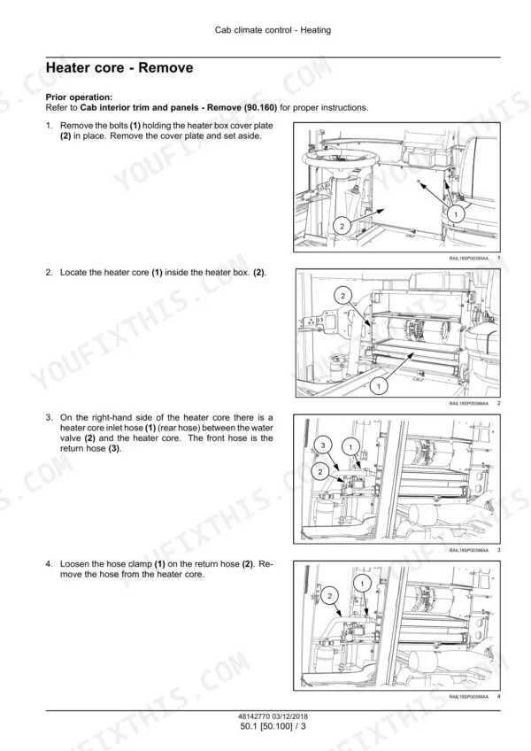
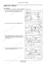
| Cab Climate Control | 473-508 | Heater Core, Heater Control Valve, Air Conditioning, Evacuation and Recharging, Receiver-Dryer, Expansion Valve, Evaporator |
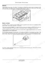
| Electrical System | 509-533 | Power Distribution, Batteries, Jumper Posts, Fuses and Relays, CAN Terminating Resistors, Grounding, Starting Circuit |
| Harnesses and Connectors | 534-939 | Machine Electrical Schematic Sheets, Chassis and Cab Harnesses, Boom Harnesses, Power Cables, Engine ECU and CAN Schematics, Connector Pinouts |
| Electronic Modules | 940-1037 | SPN and FMI Cross Reference, Module Alarms, Driveline Alarms, Input and Output Alarms, Filter and Level Tests, Pressure and Temperature Tests, HVAC Diagnostics |
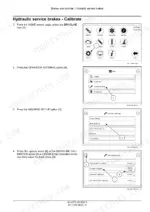
| Hydrostatic Drive Control System | 1038-1053 | Machine Level Unlock, Driveline Calibration, Joystick Calibration, Brake Calibration, Pump and Motor Calibration |
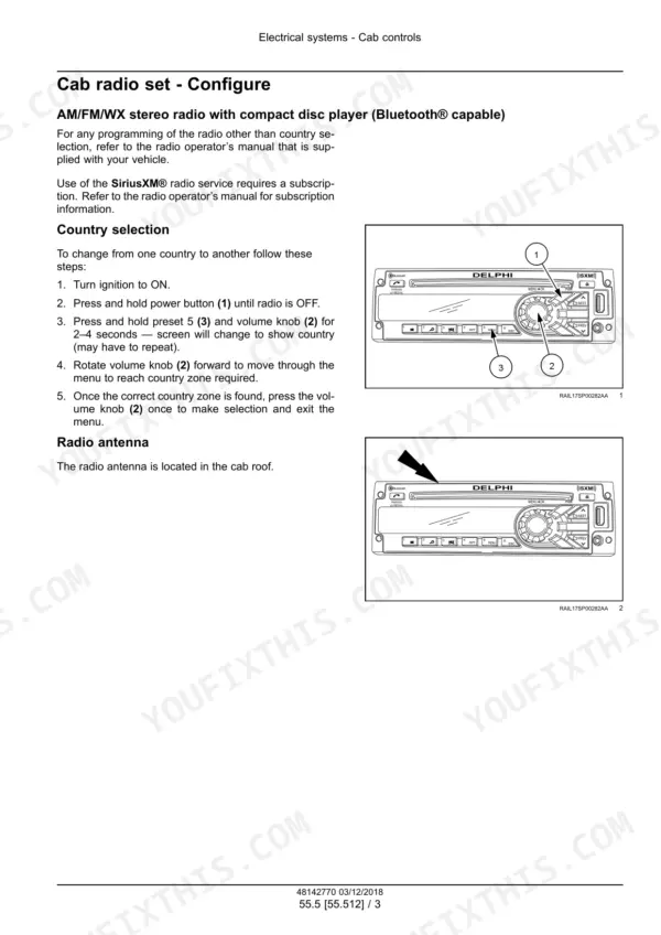
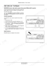
| Cab Controls | 1054-1061 | Radio, Country Selection, Antenna, Presets |
| HVAC Control System | 1062-1069 | Blower Removal, Blower Harness, Cross Plate, Heater Box Cover |
| Fault Codes | 1070-1900 | Fault Code Context, Cause, Possible Failure Modes and Solution, ECU Power Supply, Engine Sensors, Fuel Injection, SCR and DEF, CAN, Steering Sensors, Index |
| Spraying | 1901-1910 | Product Pumps 9306 and 9307, SV1 on/Off Coil, SV2 PWM Coil, Hydraulic Check Valve, Case Drain Lines |
| Platform, Cab, Bodywork and Decals | 1911-1971 | Instructional Seat, Cab Trim, Doors, Handrails, Operator Seat, Hood, Side Panels |
| Special Tool Index | 1972-1973 | Planetary Drive and Hub Tools, Service Brake Tools, Pump Alignment Fixtures, Pressure Gauge Hose Assembly |
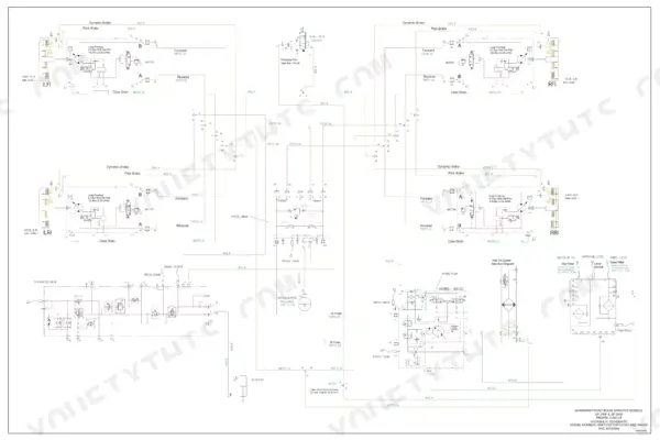
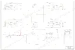
| Electrical and Hydraulic Schematics | 1974-1983 | Electrical Schematic 48180592, Propel Circuit, AUX Circuit, Boom Circuits, Autoboom, Tread Width, Float Option, 4WS Option |
Quick Reference Specifications
| Specification | Value | Page |
|---|---|---|
| Engine | FPT NEF 6.7L Tier 4B 212 kW ( 310 Hp) | p. 26 |
| Engine oil capacity, without oil filter | 15.9 L (4.2 US gal) | p. 23 |
| Engine oil capacity, with oil filter | 17.0 L (4.5 US gal) | p. 23 |
| Coolant capacity | Approximately 51.1 L (13.5 US gal) | p. 23 |
| Hydraulic tank capacity | Approximately 132 l (35 US gal) | p. 23 |
| Planetary hub capacity | 1479 mL (50 US fl oz) | p. 23 |
| Fuel capacity and type | 553 L (146 US gal) Ultra low sulfur diesel | p. 26 |
| Diesel Exhaust Fluid (DEF) capacity | 91 L (24 US gal) | p. 26 |
| Product tank, stainless steel 1000 gallon | 3785 L (1000 US gal) | p. 26 |
| Product tank, stainless steel 1200 gallon | 4542 L (1200 US gal) | p. 26 |
| Rinse tank standard | 568 l (150 US gal), Poly | p. 26 |
| Truss Boom (non-air) options | 120 ft, 132 ft. 135 ft | p. 26 |
| Crop clearance | 190.5 cm (75.0 in) | p. 26 |
| Wheel width adjustment | 300 - 406 cm (118 - 160 in), hydraulic adjust | p. 26 |
| Auxiliary hydraulic circuit | 166.6 L/min (44.0 US gpm) closed center | p. 26 |
| Product pump standard | Hypro 9306C - 795 l/min @ 5.5 bar ( 210 US gpm @ 80 psi) | p. 26 |
| Weight (approximate) | 13154 kg (29000 lb) | p. 26 |
| Air conditioning charge R134a | 7.5 lb | p. 248 |
| Rear wheel lug nut torque | 610 N·m (450 lb ft) | p. 468 |
New Holland Guardian SP310F Common Problems This Manual Covers
Engine Air Filter Clogged alarm on the display
Electronic modules testing lists the Engine Air Filter Clogged alarm with the filter and level tests. It gives the cause as a clogged or dirty air filter, and the fix is to replace the filter. The Engine chapter covers the air cleaner. Fault code 3005 (DTC 4B84) covers a clog or a circuit failure.
Manual Section: Electronic modules - Testing - Engine Air Filter Clogged p. 1016Cab Electrical Center alarm
Electronic modules testing traces the Cab Electrical Center alarm to blown fuses in the fuse/relay panel, and the fix is to replace the blown fuse. The Electrical System chapter covers power distribution, fuses and relays and grounding.
Manual Section: Electronic modules - Testing - Cab Electrical Center p. 1016Brake Pressure Low alarm
Electronic modules testing says that if brake pressure is less than 14 bar (200 psi), you find the source of the low brake pressure. Check the brake lines and repair as required. After the repair, Brakes and Controls covers the pressure accumulator and service brake calibration.
Manual Section: Electronic modules - Testing - Brake Pressure Low p. 1025HVAC Thermostat Error (short)
Electronic modules testing lists the HVAC Thermostat Error (short) with the HVAC diagnostics. It says the thermostat is not operating properly, and the fix is to replace the thermostat. Cab Climate Control covers the heater core, evaporator and expansion valve. HVAC Control System covers blower removal and the heater box cover.
Manual Section: Electronic modules - Testing - HVAC-Thermostat Error (short) p. 1030Frequently Asked Questions
Which New Holland Guardian sprayers and serial numbers does this service manual cover?
This is New Holland service manual 48142770, 1st edition English, dated December 2018. It covers the Guardian SP310F Tier 4B (final) sprayer, PIN YHF001227 and above. It includes Two-Wheel Steer and Four-Wheel Steer machines with a fixed axle or hydraulic axle and a 1000 gallon or 1200 gallon tank. p. 2
What engine, fuel tank and DEF tank does the SP310F have?
The engine is listed as the FPT NEF 6.7L Tier 4B, 212 kW (310 Hp). It holds 553 L (146 US gal) of ultra low sulfur diesel. The Diesel Exhaust Fluid (DEF) tank holds 91 L (24 US gal). p. 26
What product tank, boom and weight figures does the manual give?
Stainless steel product tanks are 3785 L (1000 US gal) or 4542 L (1200 US gal). The standard rinse tank is 568 l (150 US gal), poly. Truss Boom (non-air) options are 120 ft, 132 ft and 135 ft. Crop clearance is 190.5 cm (75.0 in). Wheel width adjusts hydraulically from 300 - 406 cm (118 - 160 in). Approximate weight is 13154 kg (29000 lb). p. 26
What service capacities and torque values are in the manual?
Engine oil takes 15.9 L (4.2 US gal) without the oil filter and 17.0 L (4.5 US gal) with it. Coolant is approximately 51.1 L (13.5 US gal). The hydraulic tank holds approximately 132 l (35 US gal), and each planetary hub takes 1479 mL (50 US fl oz). Rear wheel lug nuts are tightened to 610 N·m (450 lb ft). The auxiliary hydraulic circuit is 166.6 L/min (44.0 US gpm) closed center. p. 23
Does the manual include electrical and hydraulic schematics and fault codes?
Yes. The book ends with fold-out electrical schematic 48180592 and hydraulic schematics 48180594. Those cover the propel circuit, AUX circuit, boom circuits, Autoboom, tread width, float option and 4WS option. The Hydraulic systems chapter has hydraulic schematic frames. The Harnesses and connectors chapter has machine electrical schematic sheets and connector pinouts. The FAULT CODES chapter gives each code with context, cause, possible failure modes and solution. Examples are 3028 (DTC 238-12) - Oil pressure too low, and 3005 (DTC 4B84) - Air filter clog or circuit failure. p. 1974






Reviews
There are no reviews yet.