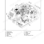
Part of the New Holland Repair Manuals.
This 104-page New Holland L-451, L-452, L-454, L-455 Skid-Steer Loader Service Manual (OEM #40045140) puts the full hydrostatic drivetrain, gear pump, and control valve procedures in your hands, right down to Cessna and Victor valve variants. Inside you get complete wiring diagrams for the alternator and regulator circuit, hydraulic schematics covering the charge and relief systems, and a troubleshooting section built around real symptoms: loader creeps, loss of propulsion, boom arms that won't hold. Set your hydrostatic charge pressure to 90 PSI (620 kPa) cracking pressure, and torque that castellated axle nut to just 2-6 in. lbs. (0.35-1.05 N-m); numbers you won't find guessing off a parts-store chart. Your alternator should read 37 amps, and the L-455 crankcase holds 7 quarts with the filter. No more chasing an electrical gremlin with a test light and hope. Bookmarked by section, it opens on any device, so bring it to the bay and get that final drive chain adjusted right the first time.
What's Inside This New Holland L-451, L-452, L-454, L-455 Manual
| System | Pages | Key Topics |
|---|---|---|
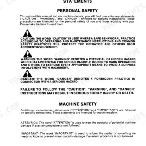
| Safety | 4-6 | - |
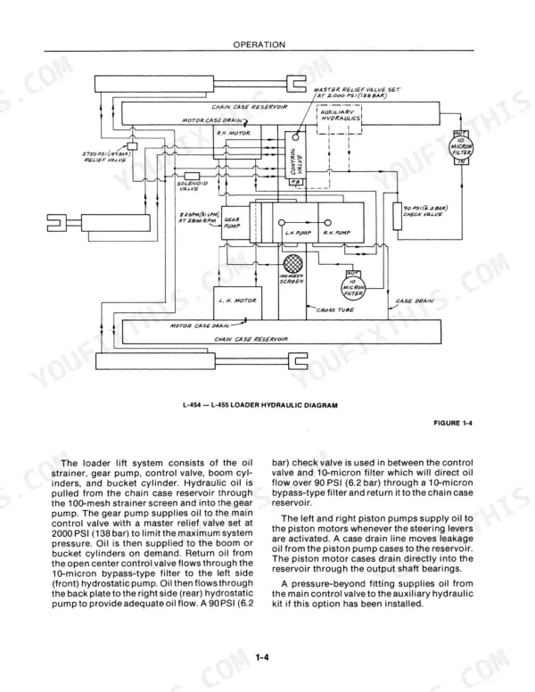
| Operation | 7-10 | Hydrostatic Transmission, Boom Hydraulic Systems, Tandem Pump, Gear Pump, Piston Pumps, Piston Motors, Steering Control Levers, Neutralizers |
| Steering Adjustments | 11-12 | Neutralizer, Neutralizer Tube Assembly, Control Arm Yokes, Control Arm Stop Bolts, Transmission Pintle Shaft, Rubber Connector |
| Hydrostatic Transmission Removal | 13-16 | Hydrostatic Pumps, Hydrostatic Motors, Tandem Pumps, Hydraulic System, Gear Pump, Steering Neutralizers, Pintle Lever Control Arms, Hydrostatic Pump Assembly |
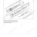
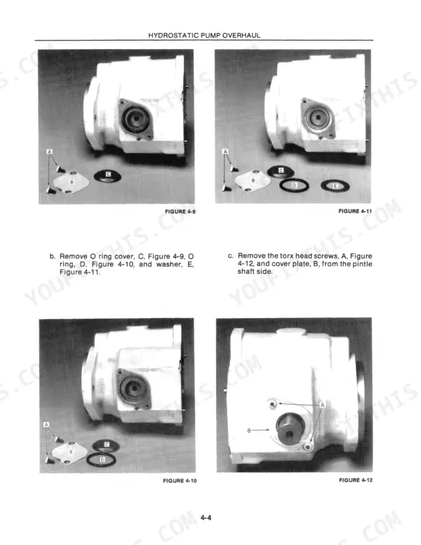
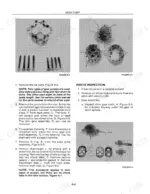
| Hydrostatic Pump Overhaul | 17-24 | Pump Housing, Hydrostatic Pump Coupler, Transmission Mount, Hydrostatic Pump Assembly, Valve Blocks, Rotating Piston Block, Piston and Shoe Assembly, Shoe Plate |
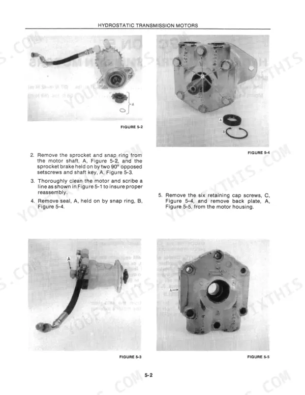
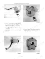
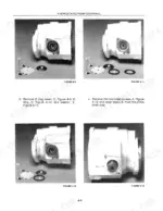
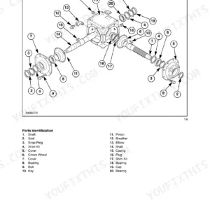
| Hydrostatic Transmission Motors | 25-30 | End Cap, Mount, Sprocket, Snap Ring, Seal, Retaining Cap Screws, Back Plate, Piston Block |
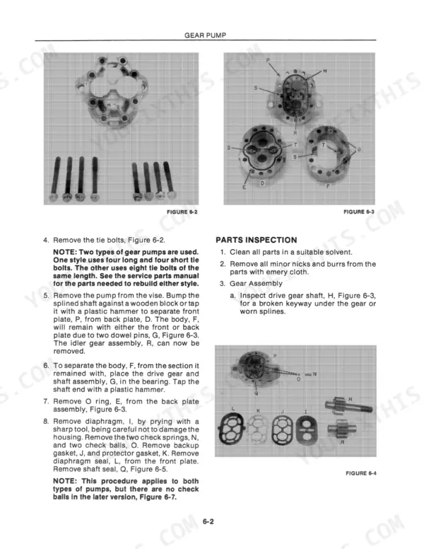
| Gear Pump | 31-36 | Drive Gear Shaft, Idler Gear Shaft, Back Plate, Front Plate, Body |
| Boom and Bucket Cylinders | 37-40 | Boom Cylinders, Bucket Cylinders, Boom Cylinder Cushion Valve |
| Control Valve | 41-48 | Main System Relief Valve, Lift Check Valves, Spools and O Rings, Cessna Control Valve, Victor Control Valve |
| Final Drive | 49-60 | Chain and Gear-Sprocket Disassembly, Axle, Intermediate Shaft, Eccentric Bearing Caps, Reassembly, Final Drive Chain Adjustment |
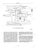
| Electrical System | 61-68 | Alternator, Regulator, Isolation Diode, Excitation Voltage Test, Regulator Bypass Test |
| Seat Activated Boom Lockout | 69-72 | Boom Lock Arms, Ignition Switch, Seat Switch, Solenoid, Hydraulic Pressure |
| Troubleshooting | 73-80 | Hydraulic System, Transmission, Electrical System, Loader Creeps, Loss of Propulsion, Boom Arms |
| Specifications | 81-100 | Diesel Engines, Gas Engines, Capacities, Electrical System, Hydrostatic Transmission, Hydraulic System |
Quick Reference Specifications
| Specification | Value | Page |
|---|---|---|
| Alternator Capacity | 37 Amp | p. 83 |
| Castellated nut torque (to turn axle) | 2 in. lbs.-6 in. lbs. (0.35 N·m-1.05 N·m) | p. 55 |
| Fuel Tank Capacity | 10 gal. (38 L) | p. 83 |
| L-455 Crankcase Capacity (includes filter) | 7 qts. (6.7 L) | p. 81 |
| Hydrostatic Charge Pressure Setting | 90 PSI (620 kPa) Cracking Pressure | p. 83 |
| Boom Cylinders Bore | 1 1/2" (38 mm) | p. 84 |
| Hydrostatic pump to engine bell housing bolt torque | 25 ft. lbs. (34 N·m) | p. 13 |
New Holland L-451, L-452, L-454, L-455 Common Problems This Manual Covers
Boom arms will not rise or rise slowly when operating the loader with a full bucket.
Measure the hydraulic fluid level and inspect the boom cylinders on page 37 for external leaks. Verify the cylinder bore measures 1 1/2" (38 mm) as specified on page 84. Rebuild the cylinders using OEM seals if internal bypass is suspected or fluid is heavily contaminated.
Manual Section: Boom and Bucket Cylinders p. 37Frequently Asked Questions
How to reset the charge indicator light?
To "reset" the charge indicator light on these models, the underlying electrical issue causing it to illuminate must be resolved. This involves performing tests on the alternator and regulator as described in the "Electrical System" section. For instance, if the regulator is found to be defective (e.g., auxiliary terminal voltage rises to 12-16 volts after bypassing the regulator), it should be replaced to restore proper charging and turn off the indicator light. p. 62
How do you fix charge indicator light fails to illuminate at the alternator regulator terminal at ignition?
Inspect the wiring harness and regulator terminal connections on page 61. Test the excitation voltage to verify the circuit is active. If the bulb is good, check the alternator capacity on page 83 to confirm it puts out the required 37 Amp. Replace the regulator if output is low. p. 61
How do you fix loud popping noise followed by drive axle cracking or failure under load during tight turns?
Remove the wheel and inspect the axle shaft for stress fatigue. Reassemble the hub components as outlined on page 49. Retighten the castellated nut on page 55 so 2 in. lbs.-6 in. lbs. (0.35 N·m-1.05 N·m) are needed to turn the axle. Replace the cotter pin immediately. p. 49
How do you fix loader creeps with control levers in neutral or hydrostatic charge pressure warning light stays illuminated?
Check the hydrostatic pump mounting bolts and transmission linkage. Verify the hydrostatic pump to engine bell housing bolt torque is set to 25 ft. lbs. (34 N·m) as shown on page 13. Test the charge pressure setting to ensure 90 PSI (620 kPa) cracking pressure on page 83. p. 13
What format is this manual in?
Instant PDF download. You get the full 104-page searchable Service Manual immediately after payment. Open it on your laptop, tablet, or phone right in the shop.
Am I able to print pages from this manual?
Yes. The PDF has no DRM restrictions, so print any page or section you need for your shop. Works with any standard printer.
Does this manual include wiring diagrams?
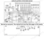
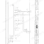
Yes, full electrical schematics are included with wire colors, connector locations, and circuit descriptions.