
Part of the New Holland Repair Manuals.
Every one of the 641 pages in this New Holland LM5020 Service Manual PDF (OEM #84559130) is aimed at one machine: your LM5020 telehandler. You get full electrical circuit diagrams with connector and component lists, hydraulic schematics for the complete circuit and control valve, and the alarm code list for the SAR anti-tipping system, calibration mode included. Open to the transmission section for variable displacement pump and motor overhauls, or work through the boom rebuild steps, from internal tube replacement to carrier chain and extension cylinder swaps. Set the hydraulic system to 230 bar and preload the front axle steering case to 40-80 Nm; those numbers came off the factory floor, not a forum thread. No more chasing wiring faults with a multimeter and a prayer. Bookmarked and keyword-searchable; pull it up on your phone next to the machine and get wrenching.
Other edition of this manual
What's Inside This New Holland LM5020 Manual
| System | Pages | Key Topics |
|---|---|---|
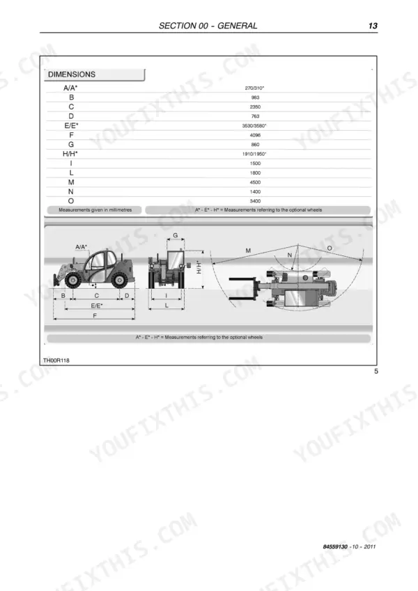
| General - Section 00 | 8-25 | Safety Rules, Product Identification, Environmental Considerations, Maintenance Techniques, Specific Sealing Compounds, Minimum Tightening Valves for Threaded Fasteners |
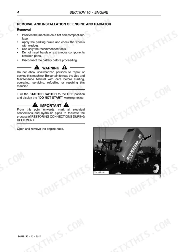
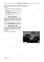
| Engine - Section 10 | 26-39 | Main Engine Specifications, Engine Model Views, Removal and Installation of Engine and Radiator, Filing the Engine Cooling System, Bleeding Air From the System, Important Warnings |
| Transmission - Section 21 | 40-125 | Variable Displacement Motor, Exchanging Seals, Exchanging the Controller, Sealing the Cover, Checking (Beginn Regulation: DA1/4, DA2, 3, 4, 5, 6), Variable Displacement Pump |
| Front Axle - Section 25 | 126-379 | Wheel Toe-In Check, Component Overhaul, Front Axle Removal Procedure, Planetary Reduction 1:6 and the Steering Case, Steering Cylinder |
| Rear Axle - Section 27 | 380-387 | Drive Shaft Removal, Reattachment, Rear Axle Removal Procedure, Overhaul, Installation |
| Brakes - Section 33 | 388-471 | Disassembly the Incoming Disc Brake, Assembly the Incoming Disc Brake, Disassembly Brake: Service Brake and Mechanic Parking Brake |
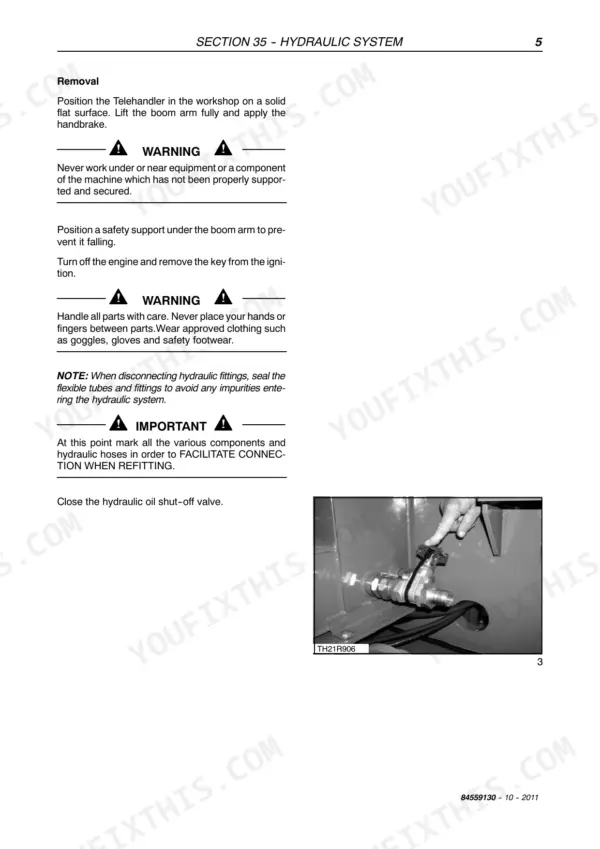
| Hydraulic System - Section 35 | 472-537 | Hydraulic System Circuit, Hydraulic Control Valve, Cylinders (Lifting Cylinder, Boom Lifting Phases, Boom Descent Phases, Lifting Cylinders Dismounting Instructions) |
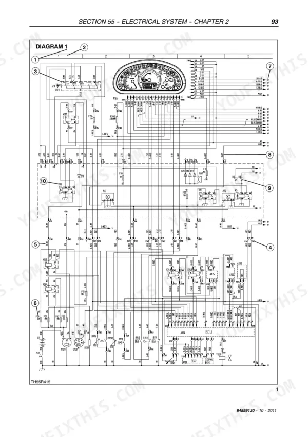
| Electrical System - Section 55 | 538-641 | Electrical System - General (Functions, Instruments Indicators, LCD Display, Inputs, Sar-Anti-Tipping System, Warnings, Electrical Connections, System Layout, Control Panel) |
Quick Reference Specifications
| Specification | Value | Page |
|---|---|---|
| Torque for the fifth screw | 10,4 Nm | p. 118 |
| Yanmar Engine cooling liquid temperature indicator sensor resistance at - (Mechanical Zero) | 1300.0 ohm | p. 549 |
| Engine Displacement | 3.319 L | p. 27 |
| Hydraulic System Operating Pressure | 230 bar | p. 23 |
| Front Axle Steering Case Preload | 40 - 80 Nm | p. 147 |
| Front Axle Crown Wheel Nut Torque | 90 - 100 Nm | p. 158 |
| Front Axle Articulation Pin Torque | 128 - 142 Nm | p. 153 |
| Brake System Slotted Nut Torque | 260 - 300 Nm | p. 396 |
| Brake System Caliper Bolt Torque | 120 - 123 Nm | p. 397 |
| Brake System Lever Torque | 10 Nm | p. 425 |
New Holland LM5020 Common Problems This Manual Covers
New Holland LM5020 hydraulic pressure low, ECU-101 code, boom will not lift rated load
Check hydraulic oil level with the boom lowered before anything else. Tee a gauge into the pressure test port and compare against the 230 bar maximum operating pressure listed on page 23. If pressure stays low with a full tank, pull the suction filter and inspect for contamination before condemning the pump or main valve.
Manual Section: Hydraulic System - Section 35 p. 472Grinding noise from the drive pump, then boom and drive functions go weak
Inspect the suction hose for internal collapse and inlet fittings for air leaks before condemning the pump; grinding usually means cavitation. Check the drive coupling for worn splines while you are in there. If you pull the drive pump, follow the variable displacement pump procedure and torque the fifth mounting screw to 10.4 Nm on reassembly, per page 118.
Manual Section: Transmission - Section 21 p. 118Machine overheats under load, temperature gauge climbs fast, ECU-310 alarm on the display
Verify fluid level first, then clean the radiator and cooler fins with compressed air; restricted airflow drives most ECU-310 alarms. Look up the code in the fault reference. If cooling checks out, test the temperature indicator sensor against the 1300 ohm mechanical zero resistance shown on page 549 before replacing it.
Manual Section: Electrical System Alarm CodesAttachment coupler will not lock or unlock from the joystick button in cab
Test fuse F20 and the joystick switch supply before touching hydraulics; most coupler failures are electrical. Trace the solenoid circuit on the wiring diagram and confirm both solenoids click when commanded. If they click but nothing moves, gauge the coupler circuit; the system runs 230 bar maximum per page 23.
Manual Section: Electrical System - Section 55Service brake pedal feels weak and parking brake will not hold on a slope
Remove the wheel and inspect pad wear and the caliper mounting. Torque caliper bolts to 120 to 123 Nm per page 397 and the slotted adjustment nut to 260 to 300 Nm per page 396. Set the parking brake lever fastener to 10 Nm, page 425, then test holding power on a grade before releasing the machine.
Manual Section: Brakes - Section 33 p. 388Frequently Asked Questions
How do I reset the service light on a New Holland LM5020?
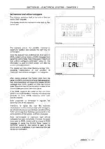
The service light is managed by the panel. Every 300 hours, the letter 'S' will flash at every switch-on along with the service interval reached. After 20 hours from reaching the table threshold, the letter 'S' and the reached hours should no longer be displayed. p. 560
What are the torque specifications for the crown wheel screws on the front axle?
The crown wheel screws on the front axle must be tightened in two stages using a criss-cross method. The initial torque wrench setting is 90 Nm, and the final torque wrench setting is 100 Nm. p. 158
What is the procedure for bleeding air from the engine cooling system?
After filling the cooling system, start the engine and run it at idle for at least five minutes. Then, increase engine revolutions to warm the coolant until the thermostat opens, which occurs at about 90°C. Once the thermostat opens, keep engine revolutions high for about 15 minutes to release all remaining air. p. 39
What is the torque specification for the brake support screws?
The screws for the brake support should be tightened using a criss-cross method to a torque setting of 49 to 51 Nm. p. 396
What is the required torque for the steering cylinder locking screws?
The steering cylinder locking screws must be tightened using a cross-tightening method to a torque setting of 90 to 100 Nm. p. 170
Is this Service Manual a digital download?
A single searchable PDF file of 641 pages, downloadable right after payment. Nothing ships, nothing waits in the mail.
Am I free to print this Service Manual?
Absolutely. No DRM or copy protection. Print the whole manual or just the pages you need. Any home or office printer works.






Reviews
There are no reviews yet.