

Part of the New Holland Repair Manuals.
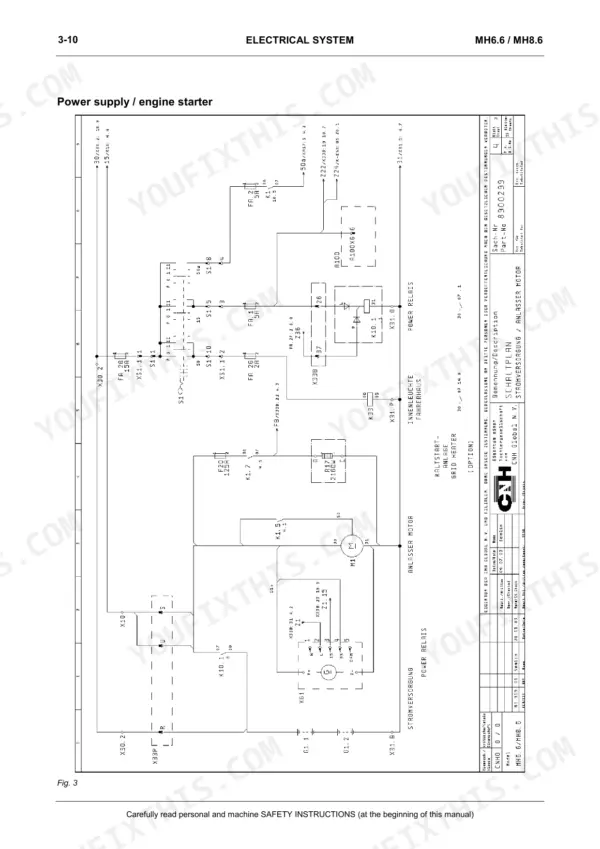
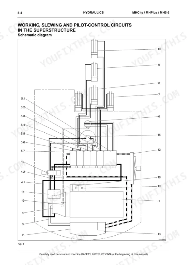
This 638-page Cnh Baumaschinen Gmbh MH6.6 / MH8.6 Hydraulic Excavator Workshop Manual (OEM #604.13.562) covers both machines in the same 638 pages, no separate booklet needed. Open it and you get full electrical circuit diagrams with connector pin assignment tables, complete hydraulic circuit diagrams for the working, slewing, pilot-control, and travel circuits, plus a dedicated calibration section for the A8V main pump and A4V slewing pump. You also get fault code listings for the Esx, Pcs, and central control unit, laid out step by step instead of buried in a glossary. Fuse the ECU circuit correctly: the power supply runs through a 30A fuse, and the central electronic unit (A100) handles speed-changer motor M10 control. No more chasing a slewing fault with a test light and a guess. Search any keyword, jump straight to the bookmarked section, and get back under the machine.
What's Inside This Cnh Baumaschinen Gmbh MH6.6, MH8.6 Manual
| System | Pages | Key Topics |
|---|---|---|
| Safety Instructions | 7-44 | Personal Safety, Before Starting Work, During Operation, Maintenance/servicing, Warning and Instruction Signs, Organizational Measures |
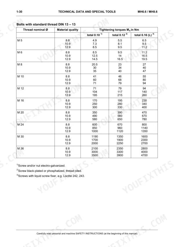
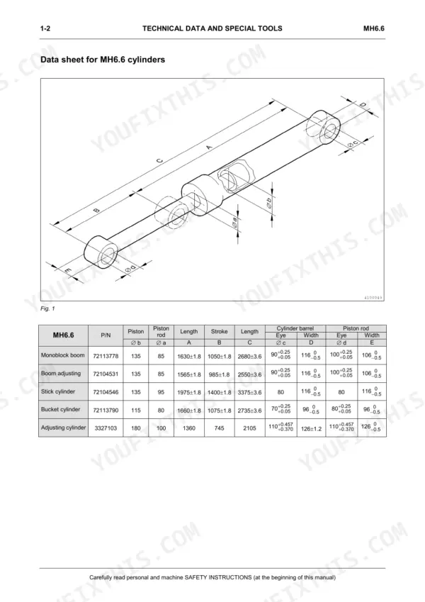
| Technical Data and Special Tools | 45-86 | Service Data General, Data Sheet for Cylinders, Conversion Tables, Calculation Examples, Tightening Torques, Special Tools for Cylinders and Gearboxes |
| Machine Structure | 87-126 | Description of Machine (Boom-Adjusting), Switches/keys, Control Elements, Multifunction Display, Superstructure Components, Undercarriage Components |
| Electrical System | 127-202 | Fundamental Notions, Fuses, Electrical Circuit Diagrams, Layout of Electrical Components, Connector Pin Assignment Tables |
| Electronics | 203-254 | Electronic Control Unit, Power Supply, Components at CAN Bus, Esx Coding, Pcs: Power Control System, Pcs Components |
| Hydraulics | 255-442 | Hydraulic System Overview, Working/slewing/pilot-control Circuits, Hydraulic Circuit Diagrams, Drive Unit, Control Block, Pilot-Control System, Travel Circuit |
| Calibration | 443-472 | Measures to Be Taken on Main Pump A8V, Measures to Be Taken on Slewing Pump A4V, Display/service/calibration (Engine on), Display/service/calibration (Engine Off) |
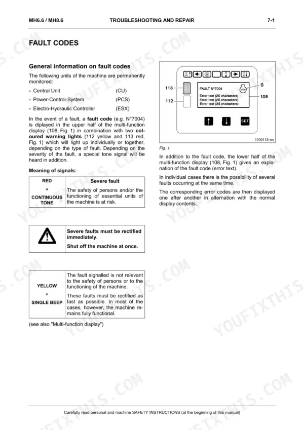
| Troubleshooting and Repair | 473-492 | General Information on Fault Codes, Fault Codes Esx, Fault Codes Pcs Unit, Fault Codes Central Unit |
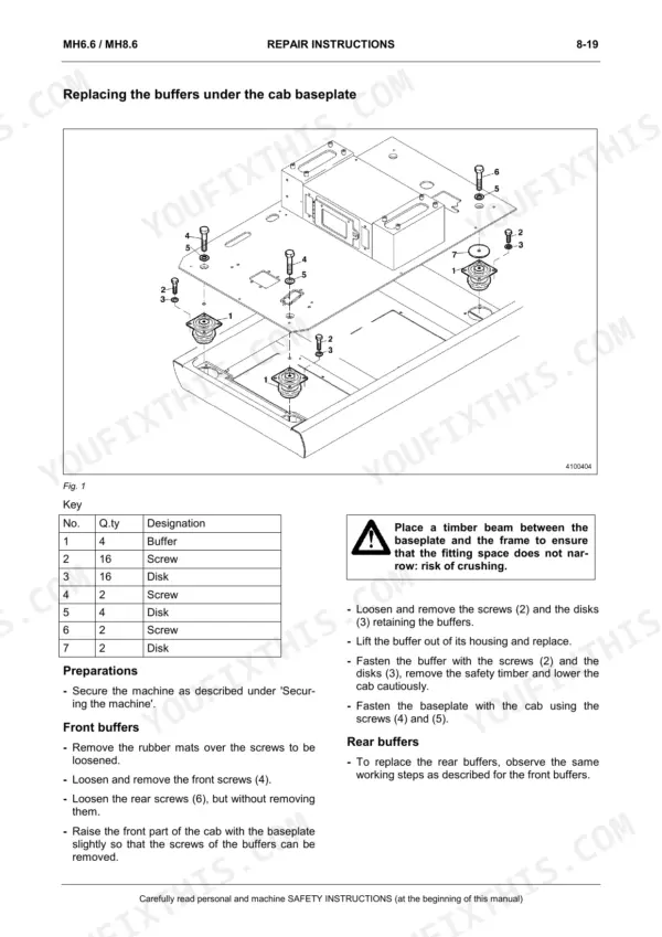
| Repair Instructions | 493-636 | Generalities, Welding Operations, Depressurizing Hydraulic System, Superstructure Components, Undercarriage Components, Equipment Components, Wear Parts |
Quick Reference Specifications
| Specification | Value | Page |
|---|---|---|
| Central electronic unit | A100 | p. 208 |
| Hydraulic system described according to the power flow in the machine and the individual functions and combined functions | 3 parts | p. 207 |
| Engine control unit (ECU) power supply | 30A fuse | p. 215 |
| Central electronic unit, including for the control of the speed-changer motor M10 | CU | p. 235 |
| Hydraulic oil temperature sensor, hydraulic system | R14 | p. 235 |
| Proportional valve for output adjustment of main pumps A8V | Y10 | p. 235 |
| Max. coil current | 850 mA | p. 248 |
| Coil resistance at 20 °C | 18 Ω ± 0,2 Ω | p. 248 |
| Coil resistance at 20°C | 450 Ω+/-20 Ω | p. 244 |