
Part of the New Holland Repair Manuals.
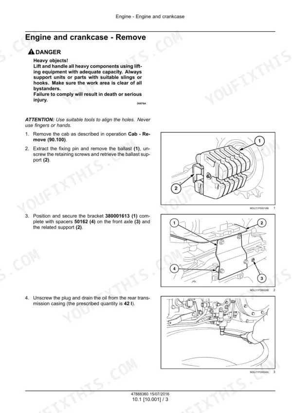
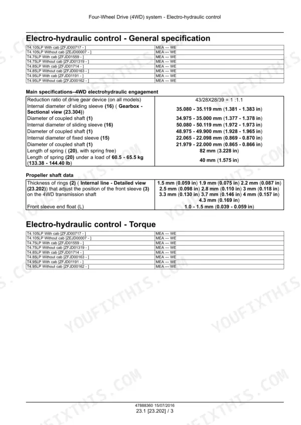
Factory service manual for the New Holland T4F and T4LP series - T4.75F, T4.85F, T4.95F, T4.105F and the low-profile T4.75LP, T4.85LP, T4.95LP, T4.105LP, Tier 3 machines built 2016-2018 (publication 47888360, dated 15/07/2016). This is the real workshop book: engine removal and installation, Luk 11 in clutch overhaul with wear limits and refacing dimensions, mechanical and power shuttle transmissions, creeper and Hi-Lo, 4WD gearbox, front and rear axles down to the planetary drives, PTO, brakes, steering, cab A/C, and the full electrical section with schematic sheets 01-29, connector codes, and 5-digit fault code listings. Capacities, clearances, and torque figures are printed where you need them, plus a special tool index cross-referenced to each procedure.
What's Inside This New Holland T4.75F–T4.105LP Manual
| System | Pages | Key Topics |
|---|---|---|
| Engine | 21-34 | Engine and Crankcase, Engine Removal and Installation, Engine Starting System, Cold Start Aid |
| Clutch | 35-68 | Clutch Hydraulic Release Control, Clutch Mechanical Release Control, Clutch and Components, Clutch Overhaul, Clutch Troubleshooting |
| Transmission | 69-182 | Mechanical Transmission, Power Shuttle Transmission, Creeper, Reverser, Hi-Lo Unit |
| Four-Wheel Drive (4WD) System | 183-214 | Electro-Hydraulic Control, 4WD Gearbox, Drive Shaft |
| Front Axle System | 215-396 | Powered Front Axle, Front Bevel Gear Set and Differential, Final Drive Hub, Steering Knuckles, And Shafts, Final Drives |
| Rear Axle System | 397-444 | Powered Rear Axle, Rear Bevel Gear Set and Differential, Planetary and Final Drives, Spur Gear and Final Drives |
| Power Take-Off (PTO) | 445-502 | Rear Mechanical Control, Front Power Take-Off (PTO) |
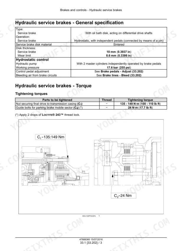
| Brakes and Controls | 503-562 | Hydraulic Service Brakes, Parking Brake or Parking Lock, Trailer Brake Hydraulic Control |
| Hydraulic Systems | 563-732 | Fixed Displacement Pump, Remote Control Valves, High Flow Hydraulics, Main Lift System, Three-Point Hitch Control |
| Hitches, Drawbars, and Implement Couplings | 733-810 | Rear Three-Point Hitch (General Specification, Torque, Install/Join/Disassemble/Assemble) |
| Steering | 811-856 | Steering Control, Hydraulic Control Components |
| Wheels | 857-864 | Front Wheels (Technical Data, Toe-In Adjustment) |
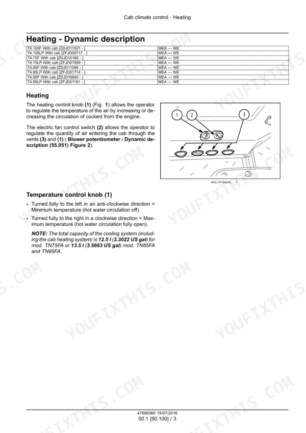
| Cab Climate Control | 865-936 | Heating, Ventilation, Air Conditioning |
| Electrical System - Overview and Harness Layouts | 937-1023 | Electrical System Overview, Harnesses and Connectors, Trailer Brake Circuit |
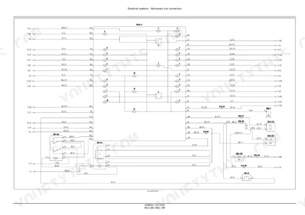
| Electrical System - Schematic Sheets 01-29 | 1024-1662 | Instrument and Sensor Circuit, Power Take-Off and Control Valves, Power-Shuttle 16+16 and 32+16, Hi-Lo Circuits, 4WD Electrohydraulic Circuit, Trailer Brake, Grid Heater, Diagnostics Connection and CAN Line |
| Electrical System - Components | 1663-1872 | Engine Starting System, Alternator, Battery, Electronic Modules, Cab Heating Ventilation and Air-Conditioning Control, Cab Hitch Controls, Rear Three-Point Hitch Electronic Control, External Lighting, Warning Indicators Alarms and Instruments |
| Electrical System - Fault Codes | 1873-2186 | Fault Code Descriptions with Possible Failure Modes and Solution Steps, Control Module Identification, Connector and Pin Level Diagnostics |
| Platform, Cab, Bodywork, and Decals | 2187-2227 | Cab Remove/Install (model+serial Specific), Cab Interior Console, Sun Protections, Cab Doors and Hatches Remove/Install |
| Special Tool Index | 2228-2239 | Special/Genuine Tool Cross-Reference Index (Tool Part Number to Procedure and Page, Not a Repair System) |
Quick Reference Specifications
| Specification | Value | Page |
|---|---|---|
| Rear transmission, gearbox, hydraulic lift, P.T.O. and hydraulic steering capacity | 44 I (11.62 US gal) | p. 18 |
| Fuel tank capacity (Standard) | 77 I (20.34 US gal) | p. 18 |
| Engine oil sump capacity | 8.5 I (2.25 US gal) (T4030F, T4040F) / 9.5 I (2.51 US gal) (T4050F, T4060F) | p. 18 |
| Cooling system capacity (With cab) | 13.5 I (3.57 US gal) | p. 18 |
| Cooling system capacity (Less cab) | 10.5 I (2.77 US gal) | p. 18 |
| Front axle housing casing capacity | 2.8 I (0.74 US gal) | p. 18 |
| Clutch driven plate thickness (Main clutch (9)) | 9.6 - 10.4 mm (0.37795 - 0.4094 in) | p. 44 |
| Clutch driven plate thickness (P.T.O. clutch (11)) | 7.3 - 7.9 mm (0.2874 - 0.3110 in) | p. 44 |
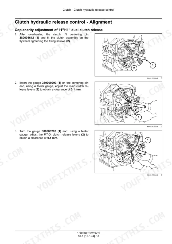
| Clutch release lever coplanarity adjustment (11"/11" dual clutch) | 0.1 mm | p. 38 |
| Main clutch pedal travel (without cab) | 148 - 152 mm | p. 40 |
| Main clutch pedal travel (with cab) | 158 - 162 mm | p. 40 |
| Clearance between P.T.O. clutch release sleeve and housing | 0.060 - 0.136 mm (0.0024 - 0.0054 in) | p. 44 |
| Clutch/flywheel retaining bolts torque (11 in/11 in) | 20 - 25 N·m (15 - 18 lb ft) | p. 44 |
| Bolts or nuts securing creeper clutch casing to the engine (C8) torque | 117 - 129 N·m (86 - 95 lb ft) | p. 72 |
| Clutch cover height calculation formula | C = 71.4 + A | p. 55 |
| Diagnostic trouble code format | 5-digit numeric code + description, e.g. 14092 (Transmission output speed shorted to ground), not SPN.FMI/E-code | p. 2160 |
| Speed sensor SEN-129 resistance | approx. 680 ohm at 20C (68F) | p. 2160 |
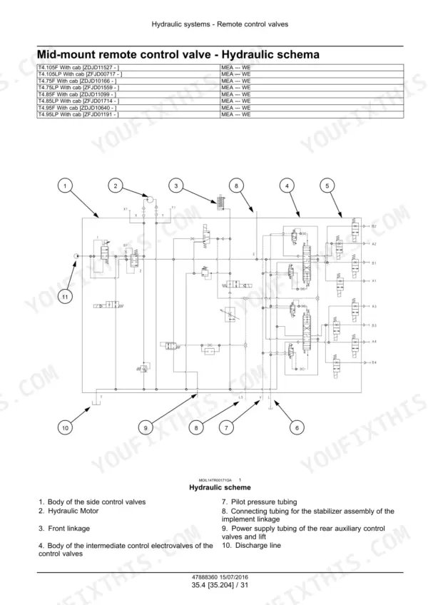
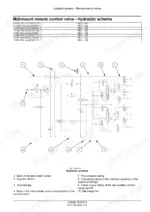
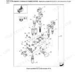
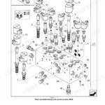
| Hydraulic diagrams included | 3: main hydraulic diagram, mid-mount remote valve schema (ISO ports A1-A4/B1-B4), front lift valve body diagram | p. 601 |
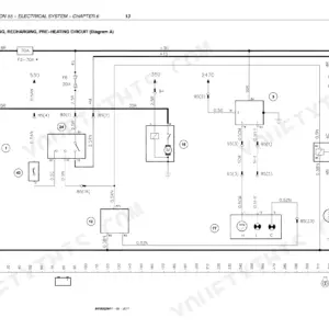
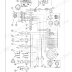
| Wiring/electrical schematics included | sheets 01-29, section 55.100, with connector/sensor codes | p. 1028 |
New Holland T4.75F–T4.105LP Common Problems This Manual Covers
Clutch slips, drags, or the pedal feels wrong after years of loader and orchard work
The Clutch section walks the full overhaul: measure driven plate thickness against the 9.6 - 10.4 mm main and 7.3 - 7.9 mm PTO limits, set release lever coplanarity to 0.1 mm, check sleeve-to-housing clearance, and verify pedal travel of 148 - 152 mm without cab or 158 - 162 mm with cab.
Manual Section: Clutch - overhaul, adjustments, and troubleshooting p. 38Hydraulics weak, jerky, or the three-point hitch will not lift under load
Start in the Hydraulic systems chapter with the main hydraulic diagram to trace the circuit from the fixed displacement pump through the remote valves to the main lift, then follow the pump test and lift control procedures to isolate pump wear from valve or linkage faults.
Manual Section: Hydraulic systems - fixed displacement pump, main lift, remote control valves p. 601PTO will not engage cleanly or keeps driving after disengagement
The PTO section covers the rear mechanical control adjustment, and the clutch chapter gives the PTO clutch wear data: cerametallic plate thickness limit of 7.3 - 7.9 mm and release sleeve clearance of 0.060 - 0.136 mm, so you can tell a linkage adjustment from a worn clutch pack before splitting the tractor.
Manual Section: Power Take-Off (PTO) - rear mechanical control; Clutch - PTO clutch specifications p. 44No-start, intermittent shutdowns, or electrical gremlins in sensors and switches
Use the Electrical systems section: schematic sheets 01-29 identify every connector and harness run, sensor specs give hard pass/fail numbers like 680 ohm on speed sensor SEN-129, and the 5-digit fault code tables pair each code with failure modes and a fix procedure.
Manual Section: Electrical systems - schematics 01-29, harnesses and connectors, fault codes p. 1668Frequently Asked Questions
Does this manual explain the fault codes on the T4F/T4LP display?
Yes. These Tier 3 tractors use bare 5-digit codes, not SPN.FMI pairs. The manual lists each code with a plain description, possible failure modes, and a solution block - for example 14092, transmission output speed shorted to ground. It also gives the sensor checks to back it up, like speed sensor SEN-129 reading about 680 ohm at 20 C (68 F). p. 2160
Are wiring diagrams and hydraulic schematics included?
Electrical is covered properly: schematic sheets 01-29 in section 55.100 with connector codes (C1A, C6A), sensor IDs (SEN-123/129/130), and module references like MOD-11. Hydraulics get three diagrams - the main hydraulic diagram, the mid-mount remote valve schema with ISO ports A1-A4/B1-B4, and the front lift valve body. That is enough to trace the circuits, but it is not a full hydraulic schematic set, so know that before you buy it only for hydraulic prints.
Will this help me overhaul the clutch?
That is where this book earns its money. It covers both the Luk 11 in/11 in dual clutch and the 11 in single plate: release lever coplanarity within 0.1 mm, main driven plate thickness 9.6 - 10.4 mm, PTO plate 7.3 - 7.9 mm, flywheel refacing limits with the C = 71.4 + A cover height formula, and torque figures such as 20 - 25 N·m for the clutch-to-flywheel bolts and 117 - 129 N·m for the casing-to-engine nuts. p. 44
Does it list fluid capacities and which models they apply to?
Yes, with metric and US units side by side: rear transmission, gearbox, lift, PTO and steering share 44 L (11.62 US gal) with a 42 L drain quantity; engine sump is 8.5 L or 9.5 L depending on model; cooling system 10.5 L without cab, 13.5 L with cab; front axle housing 2.8 L plus 1.0 L or 1.75 L per final drive depending on front brakes. p. 18
Which exact tractors does this manual fit?
The narrow F (orchard) and LP (low profile) versions of the T4 range: T4.75F, T4.85F, T4.95F, T4.105F and T4.75LP, T4.85LP, T4.95LP, T4.105LP, model years 2016-2018 with Tier 3 engines. If you have a standard-width T4 PowerStar or a Tier 4 machine, this is not your book - the procedures and schematics differ.





Reviews
There are no reviews yet.