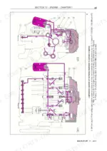
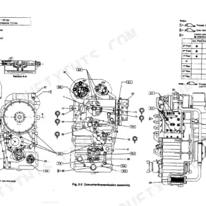
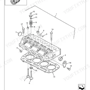
Part of the New Holland Repair Manuals.
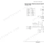
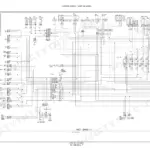
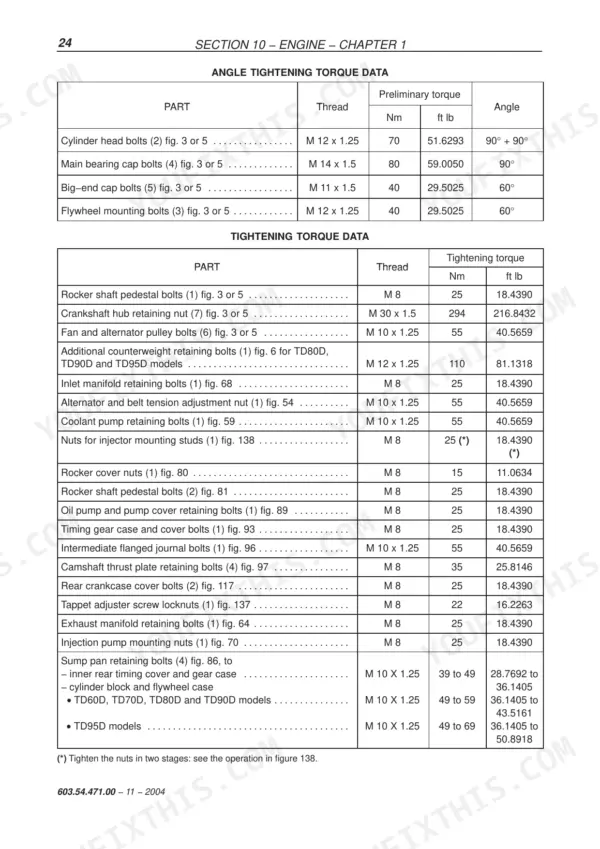
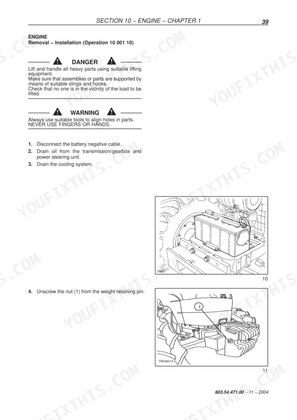
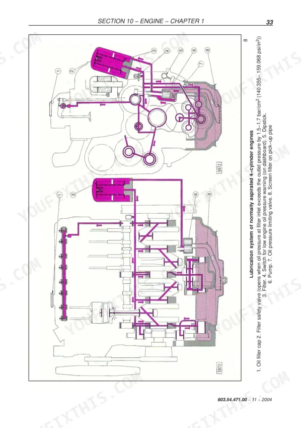
Every one of the 610 pages in this New Holland TD95D repair manual PDF (OEM #603.54.471.00) serves the whole TD-D tractor family: TD60D, TD70D, TD80D, TD90D, and TD95D. Inside: factory wiring diagrams for cab and non-cab models, hydraulic lift schematics with full circuit operation, and fault diagnosis charts for everything from the Bosch injection pump to the hydrostatic steering valve. You also get bench overhaul procedures for the engine, clutch, gearbox, rear axle, PTO, brakes, and cab air conditioning, each backed by cross-sectional views and special tool lists. Pull the cylinder head bolts down to 70 Nm plus two 90-degree turns; main bearing caps get 80 Nm plus 90 degrees. Your tractor is dead in the field, and forum guesses won't restart it. Bookmarked with a full text layer: search any spec, jump to any section, and start wrenching.
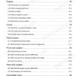
What's Inside This New Holland TD60D–TD95D Series Repair Manual
| System | Pages | Key Topics |
|---|---|---|
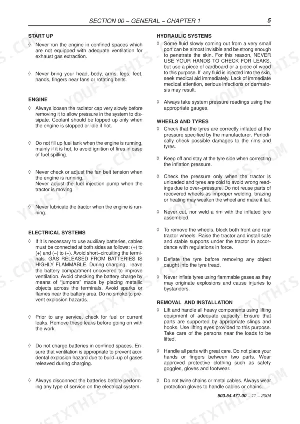
| General | 13-18 | General Instructions, Spare Parts, Equipment, Safety Rules, Consumables |
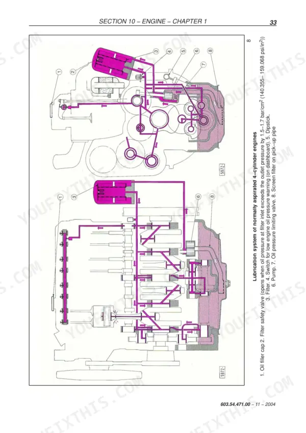
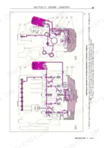
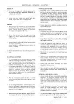
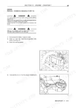
| Engine | 19-148 | Engine System (Injection Pump Calibration Data, Torque Settings, Tools, Cross-Sectional Views, Lubrication and Cooling System Diagrams, Fault Diagnosis, Engine Removal-Installation, Engine Bench Overhaul, Checks, Measurements and Repairs, Radiator Removal-Installation, Crankshaft Front Oil Seal Removal Installation, Coolant Pump Removal Installation, Cooling System Thermostat, Bosch Injection Pump Removal Installation, Bosch Injection Pump Timing, Bosch Injection Pump Air Bleeding, Injectors Removal Installation, Valve Clearance Adjustment, Coolant Pump Overhaul, Compression Test) |
| Clutch | 149-170 | Clutches (Tightening Torques, Tools, Cross-Sectional Views, Clutch Troubleshooting, Removal - Installation, Overhaul, Minimum Permissible Dimensions After Refacing, Adjustments, Main and PTO Clutch Control Linkage) |
| Transmissions | 171-200 | Mechanical Transmission, Reverser Unit, Drive Lines, Front Axle Differential, Rear Axle Transmission |
| Drive Lines | 201-208 | Main Specification, Torque Settings and Tools, Cross-Sectional Views, Transmission Shafts and Guard, Drive Gear Housing, Drive Gear Housing Removed |
| Front Axle Mechanical Transmission | 209-250 | Main Data, Tightening Torques, Tools, Cross-Sectional Views, Description and Operation, Complete Front Axle. Removal - Installation, Front Axle. Removal - Installation |
| Rear Axle and Transmission | 251-298 | Main Data, Tightening Torques, Special Tools, Cross-Sectional Views, Description and Operation and Troubleshooting, Transmission-Gearbox Casing Removal-Installation |
| Power Take--Off | 299-320 | Mechanical Power Take-Off, PTO Shaft, PTO Clutch, PTO Speed Selector |
| Brakes | 321-340 | Braking System (Main Data, Tightening Torques, Cross-Sectional Views, Description & Operation, Tools - Troubleshooting, Front Brake Assembly Mod. TD60D and TD70D Removal and Refitting - Overhauling on the Bench, Service Brake Removal and Refitting, Removal-Refitting of Front Brake Pumps, Bleeding Air From the Front Braking System, Service Brake Pedals Travel, Parking Brake Travel Adjustment) |
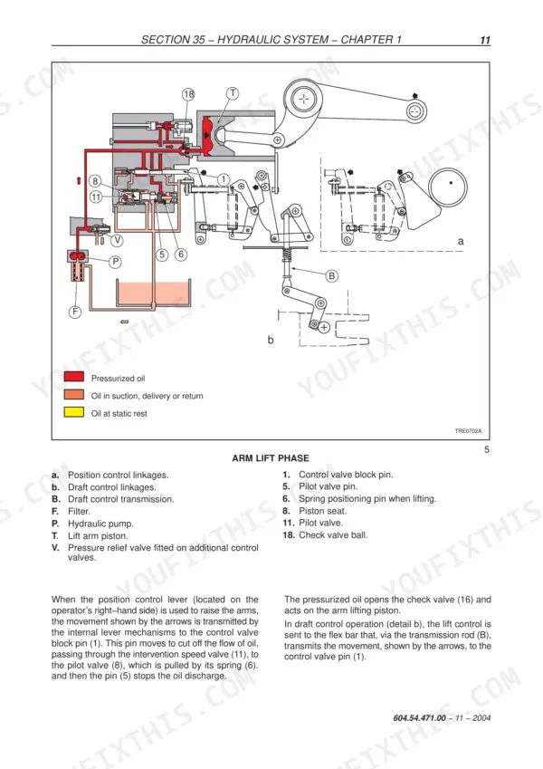
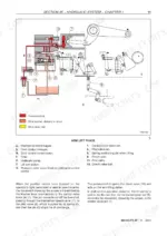
| Hydraulic System | 341-400 | Rear Mechanical Hydraulic Lift (Main Specification, Tightening Torques, Tools, Cross-Sectional Views, Description & Operation, Hydraulic Circuit, Description and Operation of Lift Phases, Fault Diagnosis, Hydraulic Lift - Disassembly Reassembly, Hydraulic Lift - Bench Overhaul, Linkage Adjustment, Pressure Relief Valve - Disassembly Reassembly, Pressure Relief Valve - Setting, Lift Control Valve - Disassembly Assembly and Overhaul on Bench, Lift Pump) |
| Steering | 401-434 | Principal Data, Tightening Torques, Hydraulic Diagram, Operation, Section, Fault Diagnosis, Tools, Removal-Installation - Hydrostatic Steering Control Valve |
| Front Axle and Wheels | 435-450 | Principal Data, Sectional Views, Torque Settings, Equipment - Fault Diagnosis, Removal-Refitting-Overhaul, Wheel Hub Disassembly-Assembly, Stub Axle Overhaul |
| Cab Air Conditioning System | 451-492 | Refrigerant Recovery Station, Receiver-Dryer, Condenser, Compressor, Evaporator |
| Electrical System | 493-594 | Instruments (Analogue Instruments Introduction, Transmitter and Switch), Components (Introduction, Component Description) |
| Cab | 595-610 | Removing Parts (Control Levers, Seat and Electrical Controls - Disassembly and Reassembly, Rear Window, Handle and Lock - Disassembly and Reassembly, Left-Hand Door Exterior Handle and Lock - Disassembly and Reassembly, Left-Hand Door - Disassembly and Reassembly, Windscreen Wiper Motor - Disassembly and Reassembly, Cab Windows - Replacement) |
Quick Reference Specifications
| Specification | Value | Page |
|---|---|---|
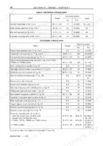
| Cylinder head bolts | 70 Nm (51.6293 ft lb) + 90° + 90° | p. 42 |
| Injection pump mounting nuts | 25 Nm (18.4390 ft lb) | p. 42 |
| Main bearing cap bolts | 80 Nm (59.0050 ft lb) + 90° | p. 42 |
| Big-end cap bolts | 40 Nm (29.5025 ft lb) + 60° | p. 42 |
| Replacement interval | 400 operating hours | p. 118 |
| Deflection | 10 to 11 mm | p. 119 |
| Injector retaining nuts 1st stage | 10 Nm (7.3756 ft lb) | p. 143 |
| Clutch/flywheel retaining bolts (mod. TD95D) | 59 Nm (43.5162 ft lb) | p. 150 |
| Torque for six bolts fastening the flexible tabs driving the main and PTO clutch pressure plates | 1.5 Nm (2.0337 ft lb) | p. 165 |
| Wheel hub bearings lock nut (C6) | 118 Nm (87.0323 ft lb) | p. 212 |
| Drive wheel hub to disc retaining nuts (C6) | 255 Nm (188.0783 ft lb) | p. 253 |
| Belt tensioner securing nut torque | 55 Nm | p. 520 |
New Holland TD60D–TD95D Series Common Problems This Manual Covers
New Holland TD90D engine overheats under load, temperature gauge climbs into the red within an hour
Check coolant level when cold and inspect the radiator core for chaff packed between the fins. Press the fan drive belt midway between pulleys; you want 10 to 11 mm of deflection, spec on page 119. Adjust at the tensioner and torque its securing nut to 55 Nm, then work the overheating chart starting.
Manual Section: Engine p. 54Engine cranks slowly or will not start in cold weather, no smoke from the exhaust
Test battery voltage and load first, then verify fuel is reaching the injection pump and bleed air from the Bosch pump following the no-start chart. If you pull injectors to check spray pattern, torque the retaining nuts in two stages on refitting, 10 Nm first and 25 Nm final.
Manual Section: Engine p. 53Three-point hitch will not raise or drops the implement slowly with engine at full throttle
Check transmission oil level before anything else, then test lift circuit pressure. The pressure relief valve should crack between 186 and 191 bar; the setting procedure is in the hydraulic lift section starting on page 376. If pressure checks good, inspect the lift control valve and linkage adjustment before condemning the pump.
Manual Section: Hydraulic System p. 376Remote valve engaged but attachment cylinder barely moves, hydraulic oil smells hot
Verify the male and female couplers are matched ISO halves and the hoses are not crossed at the remote valve. Replace worn male half seals; they bypass oil internally and heat the system fast. Test the auxiliary control valve relief pressure, which should hold at 190 bar per the setting on page 383.
Manual Section: Hydraulic System p. 383Clutch slips under heavy draft load, engagement point creeps toward the top of pedal travel
Measure the disc against the minimum permissible dimensions after refacing listed in the clutch section starting on page 149, and check pedal free play at the control linkage. On TD95D models, torque the clutch to flywheel retaining bolts to 59 Nm during reassembly, and tighten the six flexible tab bolts to only 1.5 Nm.
Manual Section: Clutch p. 149Frequently Asked Questions
What are the replacement specifications for the fuel filter?
The fuel filter cartridge should be replaced periodically every 400 operating hours. When installing a new cartridge, oil the outer part of the seal in contact with the mounting, screw it on until the seal is up against the mounting, and then tighten it by hand only, through a further 3/4 turn. p. 118
What is the correct torque setting for the cylinder head bolts?
The cylinder head bolts (2) should be tightened to a preliminary torque of 70 Nm (51.6293 ft lb), followed by an angle tightening of 90° + 90°. p. 42
What is the valve clearance for normal running when the engine is cold?
For normal running with the engine cold, the valve clearance for both intake and exhaust valves is 0.30 ± 0.05 mm (0.0118 ± 0.0020 in.). p. 22
What is the correct coolant mixture ratio for the cooling system?
The cooling system should be filled with a mixture of water and AMBRA AGRIFLU antifreeze in a 50% + 50% ratio. p. 18
How do you adjust the alternator drive belt tension?
The belt is tensioned correctly when it deflects 10 to 11 mm (0.3937 to 0.4331 in.) when a force of 78 to 98 N (17.64 to 22.05 lb) is applied at the mid-point of the run between the alternator and coolant pump pulleys. p. 119
Is this New Holland TD60D–TD95D Repair Manual a digital download?
Instant PDF download. You get the full 610-page searchable Repair Manual immediately after payment. Open it on your laptop, tablet, or phone right in the shop.
Am I able to print pages from this New Holland TD60D–TD95D manual?
Yes. Print the sections you need to take out to the shop for your own use. Standard letter or A4 paper works.