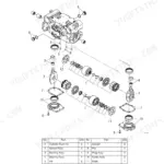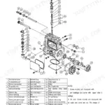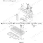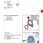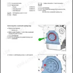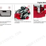

Part of the Yanmar Repair Manuals.
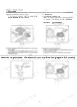
Set the cylinder head of a 3JH2LE on the bench and two numbers decide what happens next: the bore limit and the head bolt torque sequence. This Yanmar service manual, factory publication A0A5053, puts both in front of you for the 3JH2LE and 4JH2LE marine diesel engines, 213 pages of specifications, clearances, and step by step disassembly and reassembly.
It walks the whole engine: cylinder block and head measurement, pistons, crankshaft and main bearings, fuel injection pump and governor overhaul and adjustment, turbocharger, lubrication, sea water and fresh water cooling circuits, and the electrical system with wiring diagrams. When the engine is apart and there is nobody to call, this is the reference that answers the question you are standing over.
As a PDF it travels with you, on a laptop at the bench, on a tablet in the engine bay, or printed page by page as you work.
What's Inside This Manual
| System | Pages | Key Topics |
|---|---|---|
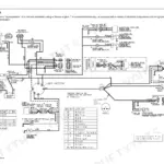
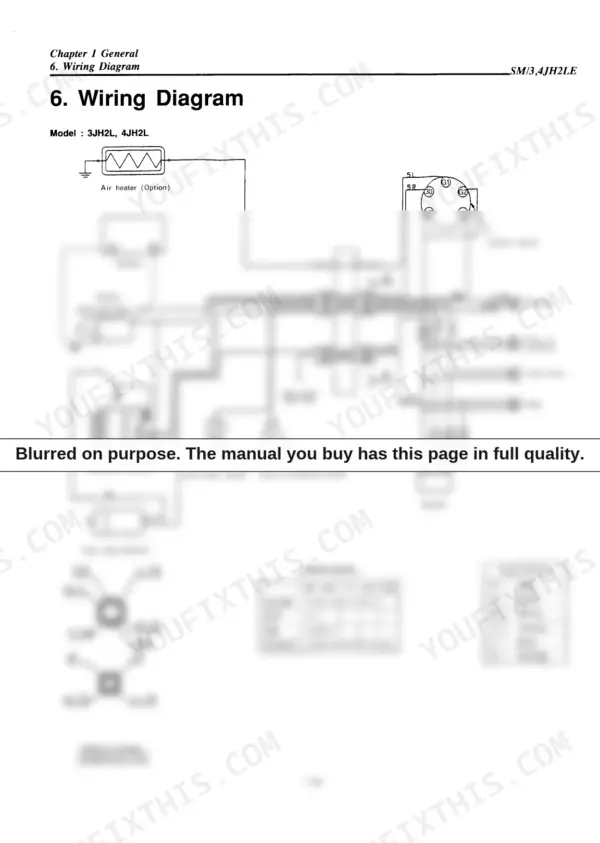
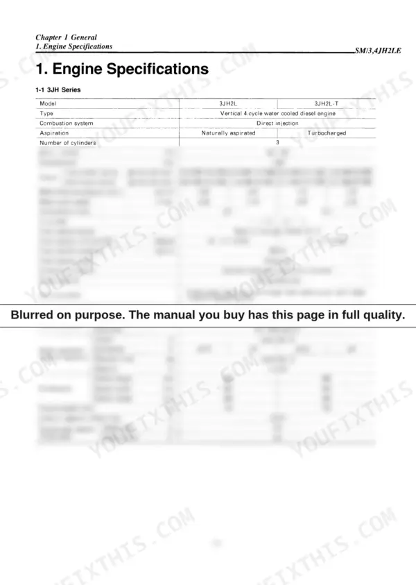
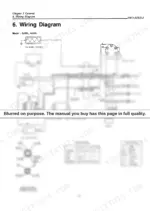
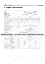
| Capter 1 General | 5-19 | Engine Specifications, Engine Cross Section, Engine Outline, Piping Diagrams, Wiring Diagram |
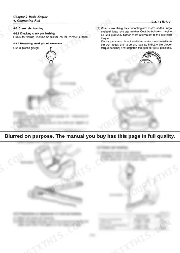
| Capter 2 Basic Engine | 20-49 | Cylinder Block, Cylinder Head, Piston and Piston Pins, Connecting Rod, Crankshaft Adn Main Bearing, Camshaft and Tappets, Timing Gear, Flywheel and Housing |
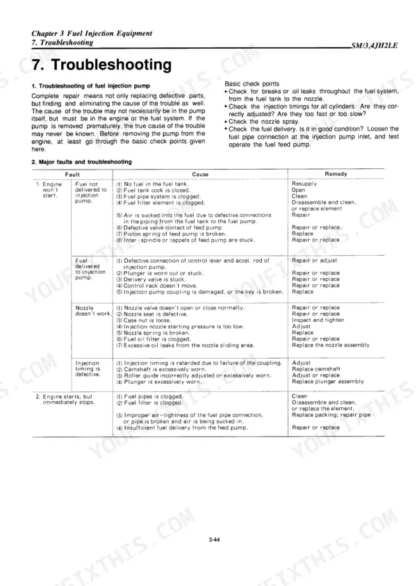
| Capter 3 Fuel Injection Equipment | 50-95 | Fuel Supply System, Disasesmbly, Reassembly and Inspection of Governor, Disassembly, Reassembly and Inspection of Fuel Injection Pump |
| Intake and Exhaust System | 96-133 | Intake Silencer, Intake Manifold, Exhaust Gas Turbocharger, Mixing Elbow, Breather |
| Lubrication System | 134-144 | Lube Oil Pump, Lube Oil Filter, Oil Pressure Control Valve, Lube Oil Cooler (Applicable Engine Model 4JH2L-Ht), Piston Cooling Nozzle |
| Cooling System | 145-160 | Cooling Water System, Sea Water Pump, Fresh Water Pump, Heat Exchanger, Pressure Cap and Sub Tank, Thermostat |
| Electrical System | 161-180 | Starter Motor, Alternator, Regulator, Warning Devices, Air Heater |
| Disassembly and Reassembly | 181-212 | Disassembly and Reassembly Precautions, Disassembly and Reassembly Tools, Bolt/Nut Tightening Torque, Test Running |
Quick Reference Specifications
| Specification | Value | Page |
|---|---|---|
| Cylinder head bolts tightening torque (First) | 3.5 - 4.5 kgf·m (25.32 - 32.55 ft·lb) | p. 29 |
| Connecting rod tightening torque | 4.5-5.0 kgf·m (32.5-36.1 ft·lb) | p. 36 |
| Governor weight nut tightening torque | 4.5-5.0 kgf·m (32.54-36.16 ft·lb) | p. 68 |
| Delivery valve holder tightening torque | 3.5-4.0 kgf·m (25.31-28.93 ft·lb) | p. 81 |
| Fuel injection nozzle starting pressure | 195-205 kgf/cm² (2773-2915 lbs/in.²) | p. 90 |
| Hole type nozzle nut tightening torque | 4-4.5 kgf·m (28.9-32.5 ft·lb) | p. 92 |
| Seawater impeller width (Standard) | 31.6-31.8 mm (1.2441-1.2519 in.) | p. 150 |
| Seawater impeller clearance at assembly | 0-0.3 mm (0-0.0118 in.) | p. 150 |
| Heat exchanger test pressure | 2 kgf/cm² (28.44 lb/in.²) | p. 156 |
| Oil filter replacement period | Every 300 hours of engine operation | p. 141 |
| Fuel pump delivery valve holder tightening torque | 3.5-4.0 kgf·m (25.31-28.93 ft·lb) | p. 81 |
| Thermostat opening temperature | 75-78°C (167-174°F) | p. 160 |