Part of the Yanmar Repair Manuals.
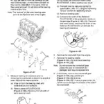
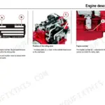
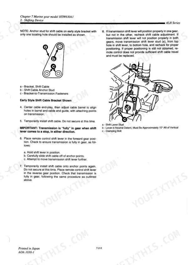
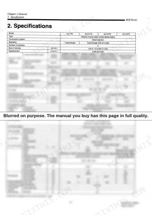
This Yanmar 4LH series Service Manual is a 398 page factory workshop guide for the marine diesel engine family, covering the turbocharged variants such as the 4LH-TE, 4LH-HTE, 4LH-DTE, and 4LH-STE. It is written in English with a full text layer, so the content is searchable and printable.
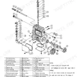
The engine is a four cylinder unit with 3.455 L displacement and a 16.4 compression ratio, and the manual documents both the distributor type and YPES-AL type fuel injection systems fitted across the range. You get complete disassembly and reassembly procedures for the basic engine, the fuel injection pumps and nozzles, the turbocharger and intake system, and the lubrication circuit.
With specifications, torque values, and service data throughout, an owner or marine mechanic can carry out a full overhaul, an injection service, or routine maintenance without guessing.
What's Inside This Yanmar 4LH series Manual
| System | Pages | Key Topics |
|---|---|---|
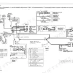
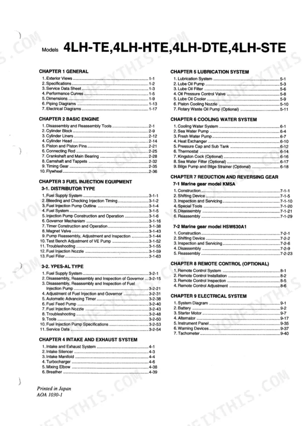
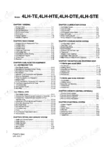
| General | 7-29 | Exterior Views, Specifications, Service Data Sheet, Performance Curves, Dimensions, Piping Diagrams, Electrical Diagrams |
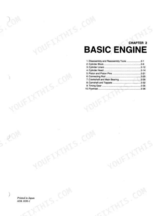
| Basic Engine | 30-68 | Disassembly and Reassembly Tools, Cylinder Block, Cylinder Liners, Cylinder Head, Piston and Piston Pins, Connecting Rod, Crankshaft and Main Bearing, Camshaft and Tappets |
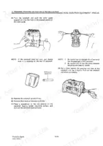
| Distributor Type Fuel Injection | 69-124 | Fuel Supply System, Bleeding and Checking Injection Timing, Fuel Injection Pump Outline, Fuel System, Injection Pump Construction and Operation, Governing Mechanism |
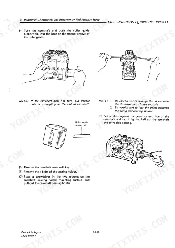
| Ypes-Al Type Fuel Injection | 125-180 | Fuel Supply System, Disassembly, Reassembly and Inspection of Governor, Reassembly and Inspection of Fuel Injection Pump, Fuel Injection Pump and Governor |
| Intake Manifold | 184-196 | Tools, Troubleshooting, Service Data, Fuel Injection Pump Specifications, Intake and Exhaust System, Intake Silencer |
| Turbocharger | 197-228 | |
| Breather | 229-237 | Mixing Elbow |
| Lube Oil Pump | 238-242 | Lubrication System |
| Rotary Waste Oil Pump (Optional) | 243-250 | Lube Oil Cooler, Lube Oil Filter, Oil Pressure Control Valve, Piston Cooling Nozzle |
| Sea Water Pump | 251-256 | Cooling Water System |
| Pressure Cap and Sub Tank | 257-263 | Fresh Water Pump, Heat Exchanger |
| Bilge Pump and Bilge Strainer (Optional) | 264-390 | Sea Water Filter (Optional), Thermostat, Kingston Cock (Optional) |
| Lubrication System | 391-398 | Lube Oil Pump, Lube Oil Filter |
Quick Reference Specifications
| Specification | Value | Page |
|---|---|---|
| All Models | ||
| Oil pressure alarm trigger point | below 0.3 kg/cm² (1.42 ~ 4.26 lb/in.²) | p. 397 |
| Fuel filter replacement interval | Every 50 hours operation | p. 123 |
| Lube oil filter replacement interval | Every 200 hours of engine operation | p. 397 |
| Fuel injection nozzle starting pressure | 195 ~ 205 kg/cm² (2773 ~ 2915 lb/in.²) | p. 122 |
| Fuel injection nozzle contact surface wear limit | 0.1 mm (0.0039 in.) | p. 121 |
| Intake silencer cleaning interval | Every 500 hours operation | p. 185 |
| Number of cylinders | 4 | p. 12 |
| Displacement | 3.455 L | p. 12 |
| 4LH-TE, 4LH-HTE, 4LH-DTE | ||
| Cylinder head bolt tightening torque (4LH-TE, -HTE, -DTE) | 1st: 5 kg-m, 2nd: 10 kg-m, 3rd: 15 kg-m | p. 14 |
| Fuel injection nozzle clamp nut tightening torque (4LH-TE, -HTE, -DTE) | 0.4 ~ 0.5 kg-m | p. 14 |
| 4LH-STE | ||
| Cylinder head bolt tightening torque (4LH-STE) | 1st: 11 kg-m, 2nd: 17 kg-m, 3rd: 19 kg-m | p. 14 |
| Fuel injection nozzle clamp nut tightening torque (4LH-STE) | 0.6 ~ 0.7 kg-m | p. 14 |