Part of the Yanmar Repair Manuals.
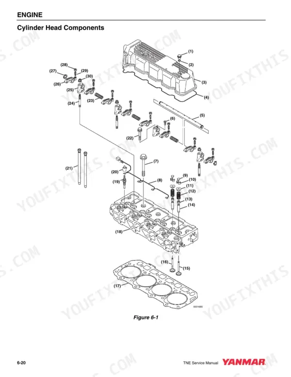
Pull the rocker cover on a Yanmar 4TNE92-NMH and the first thing you need is a valve clearance figure you can trust. This service manual, Yanmar publication 0B2991-U0001, delivers the factory procedures for the 4TNE92-NMH, 4TNE92-NMHA, and 4TNE98-NMH industrial diesels built from 2003 to 2005, whether the engine drives a generator, a pump, or sits apart on a stand.
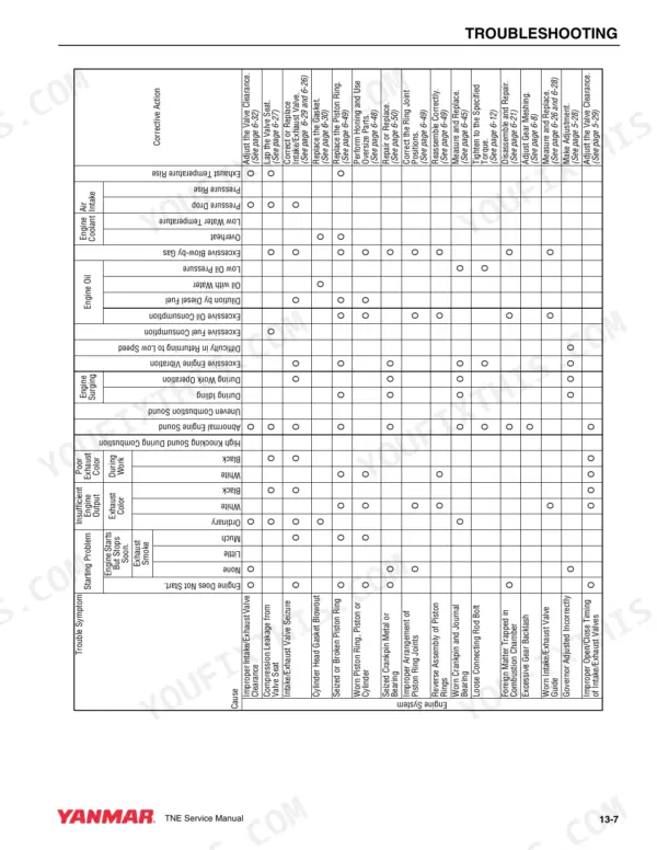
Across 280 pages it works through engine removal, valve clearance measurement and adjustment, the structure and operation of the fuel injection pump, coolant pump service, engine oil pressure checks, and full starter motor and alternator troubleshooting. A dedicated Troubleshooting section closes the book with compression pressure testing and a quick reference fault table.
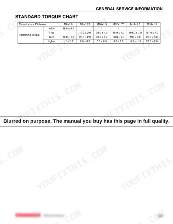
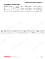
The whole thing is an English language PDF download with 340 bookmarks, ready to print a torque chart and carry to the bench, so the head goes back on in sequence and the right filter part number goes on the order the first time.
Complete the set for your 4TNE92 / 4TNE98 Series
- Parts Catalog: Yanmar 4TNE98-NMH Parts Catalog
What's Inside This Manual
| System | Pages | Key Topics |
|---|---|---|
| Introduction | 5-6 | |
| Yanmar Warranties | 7-14 | Yanmar Limited Warranty (What Is Covered by This Warranty?, How Long Is the Warranty Period?, What the Engine Owner Must Do:, To Locate an Authorized Yanmar Industrial Engine Dealer or Distributor:, What Yanmar Will Do:, What Is Not Covered by This Warranty?, Warranty Limitations:, Warranty Modifications:, Questions:, Customer Registration) |
| Safety | 15-28 | |
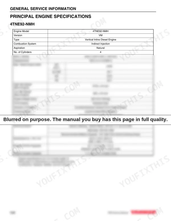
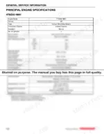
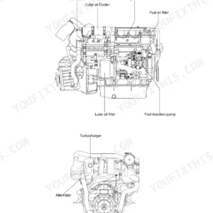
| General Service Information | 29-56 | Component Identification, Location of Labels, EPA / Arb Emission Control Regulations - Usa Only, Emission Control Labels, The 97/68/EC Directive Certified Engines, Engine Family |
| Periodic Maintenance | 57-92 | Precautions, Standard Torque Chart, Periodic Maintenance Schedule, Periodic Maintenance Procedures |
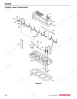
| Engine | 93-146 | Engine Service Information, Engine Special Torque Chart, Special Service Tools, Measuring Instruments, Removal of Engine, Measuring and Adjusting Valve Clearance |
| Fuel System | 147-186 | Fuel System Special Torque Chart, Measuring Instruments, Fuel System Components, Fuel System Diagram, Structure and Operation of Fuel Injection Pump, Plunger Operation |
| Cooling System | 187-204 | Measuring Instruments, Cooling System Diagram, Engine Coolant Pump Components, Before You Begin Servicing, Engine Coolant System Check, Disassembly of Engine Coolant Pump |
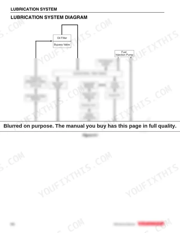
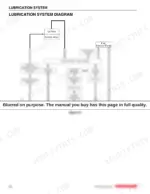
| Lubrication System | 205-216 | Oil Pump Service Information, Lubrication System Diagram, Checking Engine Oil Pressure |
| Starter Motor | 217-236 | Starter Motor Service Information, Starter Motor Troubleshooting, Starter Motor Precautions, Starter Motor Servicing |
| Alternator | 237-262 | Alternator Service Information, Alternator Troubleshooting, Alternator Precautions, Alternator Components, Alternator Servicing |
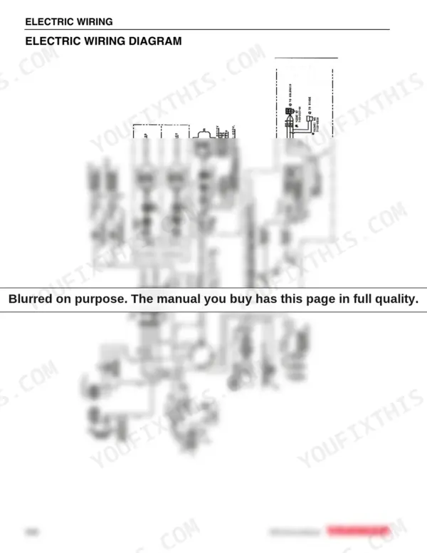
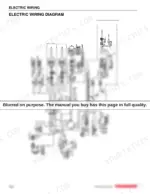
| Electric Wiring | 263-270 | Electric Wiring Precautions, Electrical Wire Resistance, Battery Cable Resistance, Electrical Wire Sizes - Voltage Drop, Conversion of Awg to European Standards |
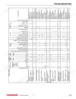
| Troubleshooting | 271-280 | Special Service Tools, Troubleshooting by Measuring Compression Pressure, Quick Reference Table for Troubleshooting |
Quick Reference Specifications
| Specification | Value | Page |
|---|---|---|
| Cylinder Head Bolts Tightening Torque | 76.0 - 83.3 ft lbs (103.1 - 112.9 N·m, 10.5 - 11.5kgf·m) | p. 104 |
| Fuel Filter Replacement Interval (Cleaning) | or every 6 months | p. 74 |
| Fuel Filter Replacement Interval (Replacement) | or every 6 months | p. 74 |
| Engine Oil Filter Replacement Interval | or every 3 months | p. 74 |
| Engine Oil Filter Part No. (Figure 5-11, (1)) | 129150-35152 | p. 84 |
| Air Cleaner Element Cleaning Interval | or every 6 weeks | p. 74 |
| Air Cleaner Element Replacement Interval (normal conditions) | or every 1 year | p. 74 |
| Fuel Injector Tightening Torque | 29.4 ft·lbs (39.2 N·m, 4 kgf·m) | p. 149 |
| Fuel Injection Pressure Standard | 1711 - 1842 psi (11.8 - 12.7 MPa 120 - 130 kgf / cm²) | p. 51 |
| Thermostat Valve Opening Temperature | 160°F (71°C) | p. 51 |
| Thermostat Full Opening Lift Temperature | 0.32 in (8 mm) or Above 185°F (85°C) | p. 51 |