
Part of the Yanmar Repair Manuals.
Set valve clearance on the 4TNE106-TB by feel and you are guessing; this Yanmar service manual gives you the written procedure instead, along with injection timing inspection, injector pressure and spray pattern testing, and no-load maximum speed adjustment for the C50R-3(R) crawler carrier. It is the factory workshop document, 374 pages in English, delivered as a PDF download.
Past the engine, it works through the whole machine: the hydraulic system unit by unit, structure and operating principles including the start and stop circuit on the 24 volt electrical system, servicing standards with wear limits and tightening torque tables, and a troubleshooting chapter for chasing symptoms back to causes.
A guessed torque or relief pressure can cost you a casting or a pump. The figures here, like the hydraulic pump's 5075 PSI maximum working pressure, come straight from Yanmar, so what you put back together runs.
What's Inside This Yanmar C50R-3(R) Manual
| System | Pages | Key Topics |
|---|---|---|
| General Cautions for Maintenance Work | 9-26 | Correct Work, Safety Precautions, Preparations, Cautions for Disassembly and Reassembly, Cautions for Removal and Installation of Hydraulic Equipment |
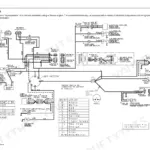
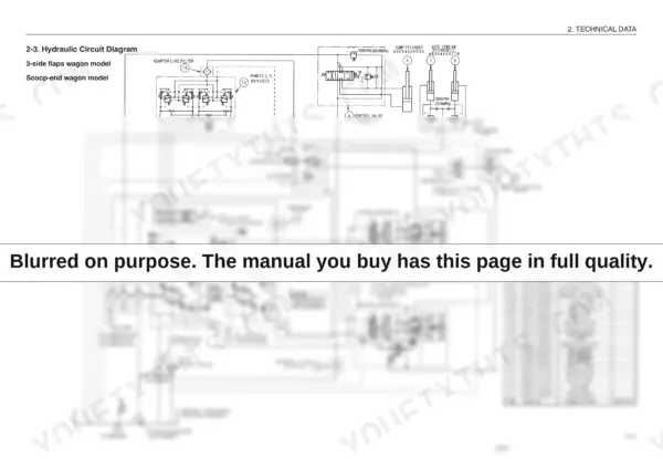
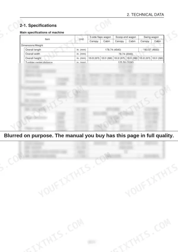
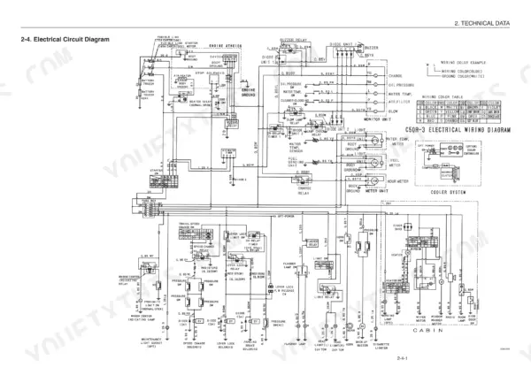
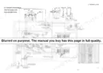
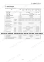
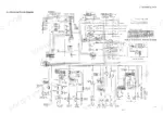
| Technical Data | 27-42 | Specifications, Outside Drawing, Hydraulic Circuit Diagram, Electrical Circuit Diagram, Main Parts Mass Chart |
| Servicing Standards | 43-60 | Machine Performance (Reference Value Table, Expendables, Methods for Inspecting Performance), Engine Servicing Standards, Servicing Standards for Parts of Undercarriage |
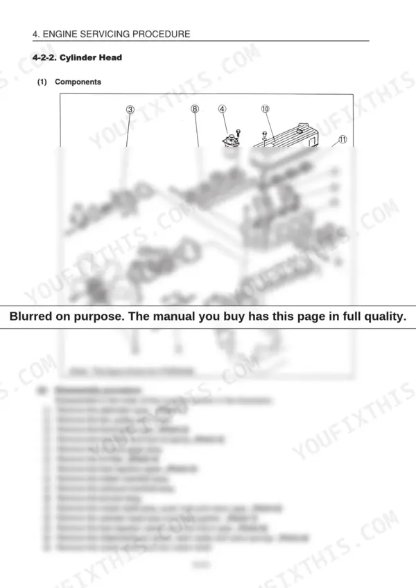
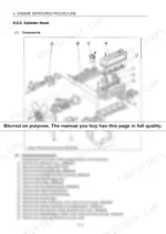
| Engine Servicing Procedure | 61-126 | Adjustment (Oil Inspection, Cooling Water Inspection, Inspecting Water Leak From Cooling Water System and Rediator, Fan Belt Tension Inspection and Adjustment, Valve Clearance, Inspecting the Fuel Injection Valve Injection Pressure and Spray Pattern, Fuel Injection Timing Inspection and Adjustment, No-Load Maximum Revolutions, Sensor Inspection) |
| Structure and Operating Principles | 127-140 | Components and Names, Power Transmission Mechanism, Electrical Equipment of the Machine (Parts Layout of Electrical Equipment), Descriptions of Engine Start/Stop Circuit |
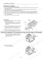
| Hydraulic System | 141-280 | Outline, Hydraulic Units |
| Service Procedures for Individual Components | 281-342 | Engine Related Components, Electrical Equipments, Undercarriage, Control System, Hydraulic System, Riggings, Swing Wagon |
| Periodic Inspection and Servicing | 343-346 | Lube Oil, Hydraulic System, Grease, Undercarriage, Steering Equipment, Electric Equipment, Fuel Oil, Cooling Water |
| Fuel, Lube Oil and Grease Recommended | 347-350 | Fuel, Lube Oil, Grease, Engine Oil, Hydraulic Oil, Travel Reduction Gear Oil, Idler, Carrier Roller |
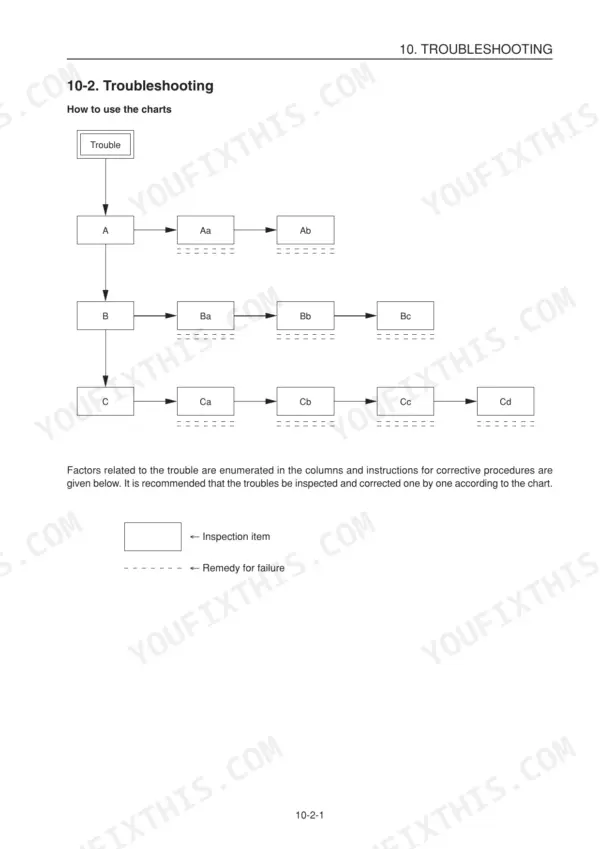
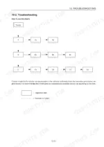
| Troubleshooting | 351-366 | HST Pump, Fuel Injection Pump, Governor, HST Troubleshooting, Travel Motor, Sprocket, Parking Brake, Control Valve |
| Option | 367-372 | Cooler, Cooler Assembly, Compressor Assembly, Condenser Assembly, Cooler Unit Assembly |
| Colophon | 373 | |
| Spine Title | 374 |
Quick Reference Specifications
| Specification | Value | Page |
|---|---|---|
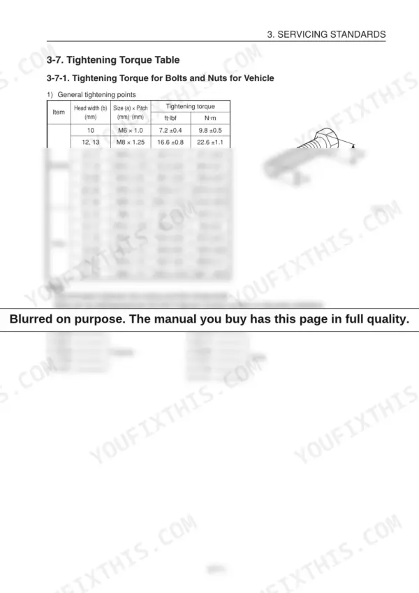
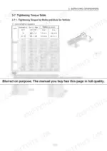
| General tightening torque for M10 x 1.5 bolts | 34.7 ±1.7 ft·lbf (47.1 ±2.4 N·m) | p. 57 |
| Hydraulic oil tank line filter replacement interval | Every 500 hrs. (After first 250 hrs.) | p. 45 |
| Hydraulic oil tank return filter replacement interval | Every 1000 hrs. (After first 50 hrs.) | p. 45 |
| Hydraulic oil recommended type | Anti-wear hydraulic oil ISO VG46 | p. 349 |
| Hydraulic oil capacity | 15.05 Gals. (57 L) | p. 349 |
| Battery type | FZ/75D23R | p. 32 |
| Battery voltage 5 hrs rate capacity | 24–64 V–A·h | p. 32 |
| Starter nominal voltage | 24 V | p. 33 |
| Braided hose (SL-06) inner diameter | 0.248 (6.3) in. (mm) | p. 22 |
| Braided hose (SL-06) thickness | 0.102 (2.6) in. (mm) | p. 22 |
| General caution for O-rings | Be careful not to twist O-rings. If an O-ring is twisted, remove the twist with the fingertips. | p. 19 |
| Seal replacement condition | If a seal is abnormal, replace it. | p. 181 |