

Part of the Case Repair Manuals.
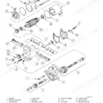
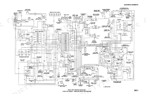
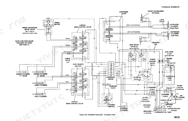
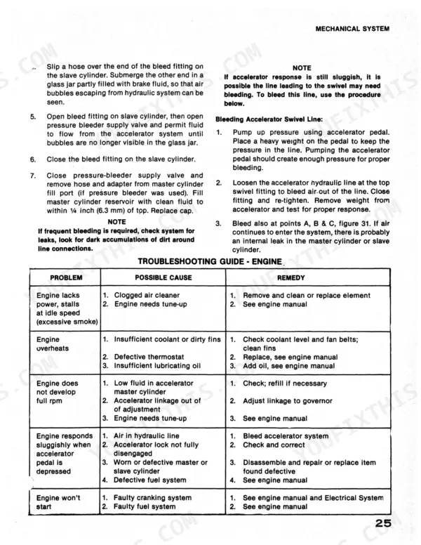
Wrenching on a Case 45? This 314-page Case 45 Cruz-Air Excavator Service Manual PDF (OEM #S406267M1) walks you through the 45 and 45 Cruz-Air excavators, from engine and torque converter to boom, dipperstick, and swing gearbox. Inside: full electrical schematics for both the 12/24 volt and 24 volt machines, hydraulic schematics for excavator and logger units, air system diagrams, and trouble charts that take you from symptom to fix. You also get page after page of cylinder and pump rebuild procedures, hoist and crowd cylinders through the main hydraulic pump. Set the main reliefs to 3000 psi (20 680 kPa) and the steering priority relief to 2000 psi, straight from the factory tables. Your excavator is down and the forums are guessing. This bookmarked PDF opens on any device; carry it to the machine on your tablet and get wrenching.
What's Inside This Case 45, 45 Cruz-Air Manual
| System | Pages | Key Topics |
|---|---|---|
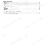
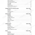
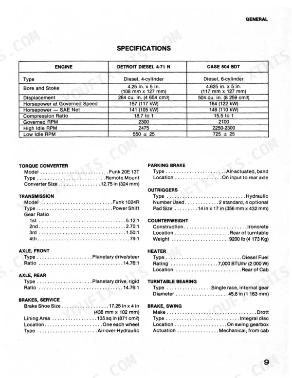
| General | 3-11 | Index, Safety, Introduction, Nomenclature, Description and Specifications |
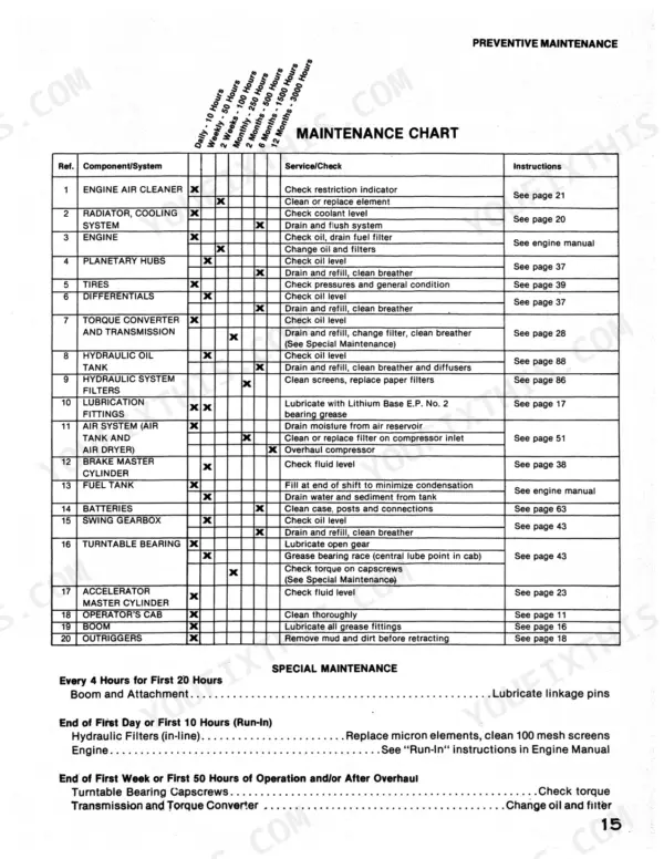
| Scheduled Preventive Maintenance | 12-20 | Introduction, Hydraulic System Operating Pressures, Capacities, Lubricants and Fluids, Maintenance Chart, List of Grease Fittings |
| Mechanical System | 21-48 | Engine, Torque Converter, Transmission, Axles, Turntable Swing, Boom and Attachments |
| The Air System | 49-58 | Introduction, Air Supply System, Service Brake System, Parking Brake, Outrigger and Fast Hoist Control, Troubleshooting |
| The Electrical System | 59-106 | Introduction, Dual Voltage System, Volt System |
| The Hydraulic System | 107-151 | Introduction, System Maintenance and Troubleshooting, Main Hydraulic System, Power Steering System, Trouble Charts |
| Cleaning Instructions and Accelerator Components | 152-154 | Cleaning Instructions, Accelerator Master Cylinder, Accelerator Slave Cylinder |
| Brake System Components | 155-193 | Brake Actuator, Brake Master Cylinder, Air Brake Control Valve, Air Compressor, Air Relay Valve, Air Solenoid Valve, Air Swivel, Wheel Brakes |
| Boom and Attachments | 194-209 | Boom Repairs, Bucket Removal, Dipperstick Removal, Bushing Replacement, Wrist-O-Twist, Grapple Head |
| Center Swivel and Collector Ring | 210-215 | Center Swivel Disassembly, Collector Ring Maintenance, Collector Ring Installation |
| Drive Shafts and Swing Gearbox | 216-225 | Drive Shaft Removal, Drive Shaft Installation, Swing Gearbox Disassembly, Swing Gearbox Assembly, House Brake |
| Hydraulic Cylinders and Pumps | 226-261 | Hoist Cylinder, Crowd Cylinder, Tool Cylinder, Steering Cylinder, Outrigger Cylinder, Main Hydraulic Pump, Steering Pump, Hydraulic Motor |
| Hydraulic Swivel and Control Valves | 262-271 | Hydraulic Swivel, Main Control Valves, Port Relief Valves, Power Sensing Valve, Steering Diverter Valve, Swing Crossover Relief Valve |
| Torque Converter and Transmission | 272-298 | Torque Converter Removal, Converter Assembly, Converter Housing Assembly, Auxiliary Pump Drive, Transmission Disassembly, Transmission Assembly, Turntable Bearing Replacement |
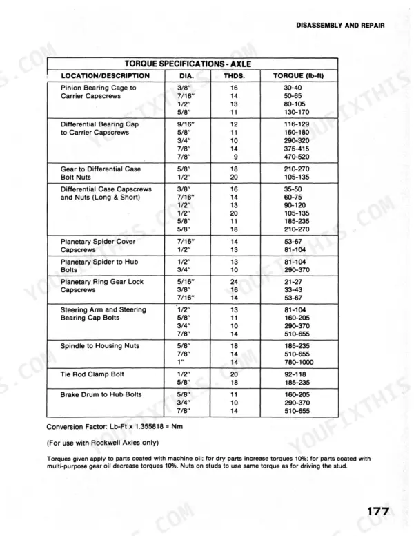
| Torque Charts and Schematics | 299-314 | Torque Charts, Air Schematic, Electrical Schematic - 12/24 Volt System, Electrical Schematic - 24 Volt System, Hydraulic Schematic - Excavator Units |
Quick Reference Specifications
| Specification | Value | Page |
|---|---|---|
| Cold Cranking Capacity | 625 amps at 0° F (-18° C) for 30 seconds | p. 11 |
| Main Relief Valve Pressure Setting | 3000 psi (20 680 kPa) | p. 124 |
| Steering Priority Relief Pressure Setting | 2000 psi | p. 13 |
| Outrigger Port Relief Pressure Setting | 800 psi | p. 13 |
| Tire Pressure (Roading) - 17.5 x 25 | 60 psi | p. 11 |
| Tire Pressure (Roading) - 23.0 x 21 | 50 psi | p. 11 |
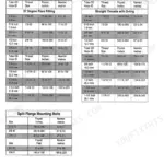
| Wheel Lug Nut Torque | 400-450 lb-ft | p. 41 |