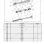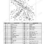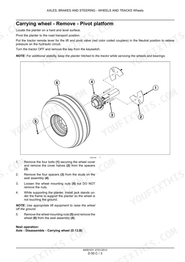
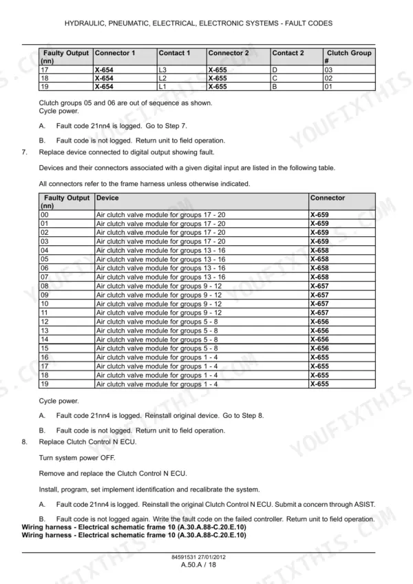
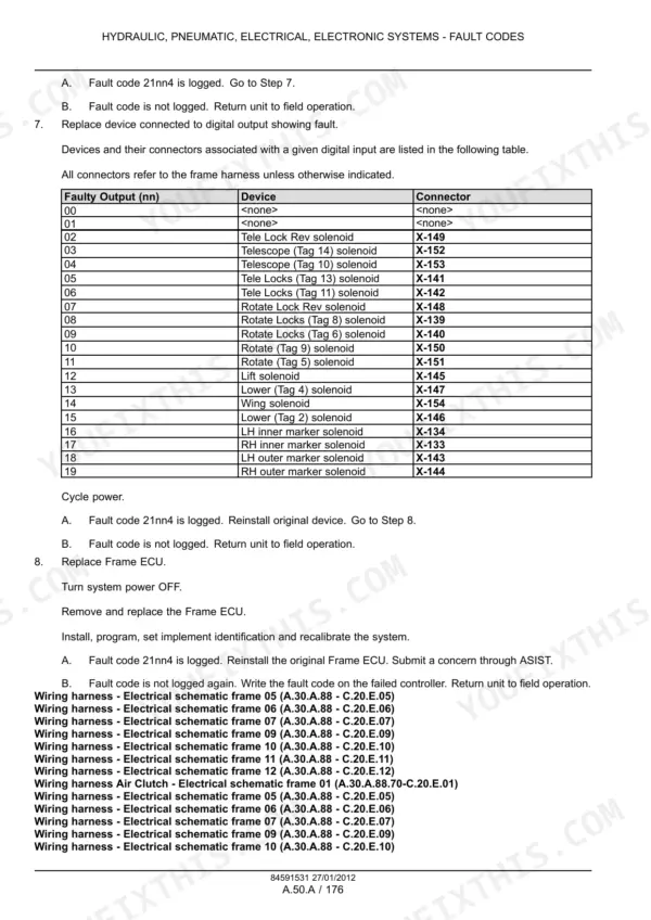
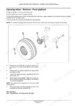
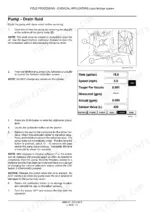
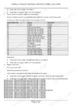
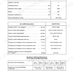
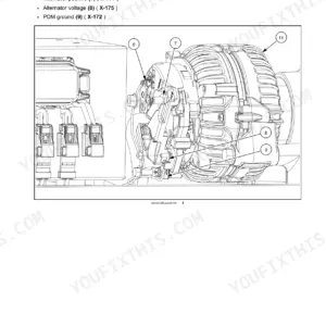
Part of the Case IH Repair Manuals.
The monitor throws a row blocked warning, the vacuum fans sound lazy and rain is forecast by the weekend. This Case IH factory service manual covers the Early Riser 1240 Pivot-Transport planter in 12 Row, 16 Row, 24 Row 20, 12/23 split row and 16/31 split row builds.
It explains the electro-hydraulic system on tractor-remote and PTO pump setups. It covers the lift and pivot, marker, coulter bar, multivalve, bulk fill and liquid fertilizer valve blocks, plus PTO pump and gearbox overhaul. Pneumatic down pressure, the AccuRow air clutch, vacuum metering and the Rate, Frame and clutch control ECUs are all included, with wiring schematics and fault procedures.
Guessing costs money. You end up buying a cartridge you didn't need, tearing down a seed meter twice or replacing a compressor when the fuse was blown. Test it once, fix it and get back in the field while the ground is fit.
What's Inside This Case IH 1240 Manual
| System | Pages | Key Topics |
|---|---|---|
| Introduction | 1-30 | Product Overview, Electro-Hydraulic Theory of Operation, Flow Guideline per Component, Hydraulic Tube and Fastener Torque, Electrical Testing, Special Tools |
| Primary Hydraulic Power System [10.A] | 31-322 | PTO Pump, Lift and Pivot, Marker, Coulter Bar, Multivalve, Bulk Hopper and Liquid Fertilizer Valve Blocks, Hydraulic Schemas, Pump and Gearbox Overhaul |
| Pneumatic System [20.A] | 323-338 | Pneumatic Down Pressure, AccuRow Air Clutch, Pilot Valve, Air Compressor |
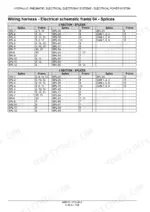
| Electrical Power System [30.A] | 339-470 | Connector Component Diagrams, Wiring Harness Component Diagrams, Crimping and Soldering |
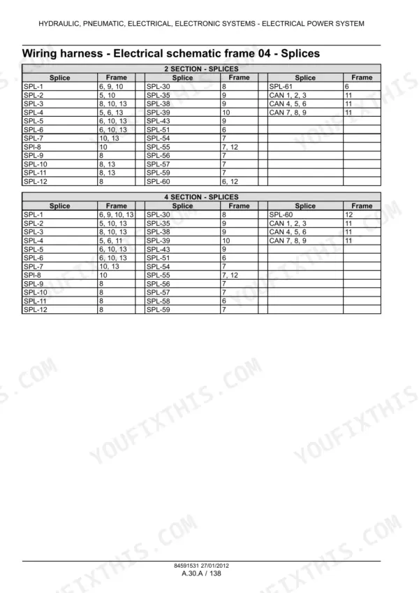
| Electrical Schematics and Lighting | 471-586 | Electrical Schematic Frames, Symbols and Legends, Speed Sensors, Power Connections, CAN Bus, Lighting System |
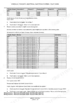
| Fault Codes [50.A], Clutch Control ECU and Display | 587-756 | Clutch Control ECU Power and CAN Faults, Seed Sensor, Flow, Speed and Down Force Display Faults |
| Fault Codes [50.A], Frame ECU and Rate ECU | 757-936 | Frame ECU Solenoid Faults, Radar and Wheel Speed, Rate ECU Power and CAN Faults |
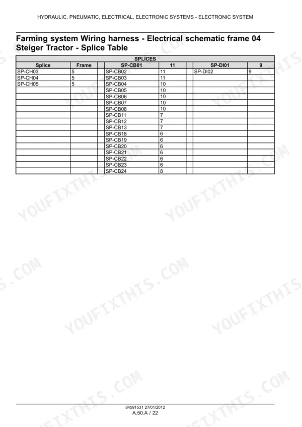
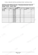
| Electronic System [50.A] | 937-1054 | Tractor-Side Farming System Harnesses, Connector Diagrams, Schematics |
| Axle and Wheels | 1055-1076 | Carrying Wheel and Wing Gauge Wheel Axle, Wheels, Ground Speed Sensor |
| Travelling, Lifting and Swinging | 1077-1156 | Counter Balance Valve, Raise Solenoids, Lift Cylinder, Pivot and Latch Solenoids and Cylinders |
| Travelling, Folding and Extending | 1157-1304 | Wing Solenoid Valve, Fold Cylinder, Tongue Solenoids, Hose Carrier, Rear Cylinder |
| Seeding, Mechanical System [10.B] | 1305-1366 | Row Unit, Pneumatic Down Pressure Layout, Gauge Wheel, Opener Disc, Seed Shoe, Closing Disc |
| Seeding, Fan System [10.D] | 1367-1408 | Fan Motor, Control Valve Cartridges, Motor Reseal |
| Seeding, Air System [10.E] | 1409-1436 | Seed Gate and Collector |
| Seeding, Metering System [10.F] | 1437-1484 | Seed Sensor, Variable Drive Motor, Seed Meter |
| Seeding, Vacuum System [10.H] | 1485-1530 | Vacuum Fan Motor and Fan, Control Valve Cartridges |
| Seeding, Marking System [10.J] | 1531-1570 | Marker Valves, Inner and Outer Marker Cylinders |
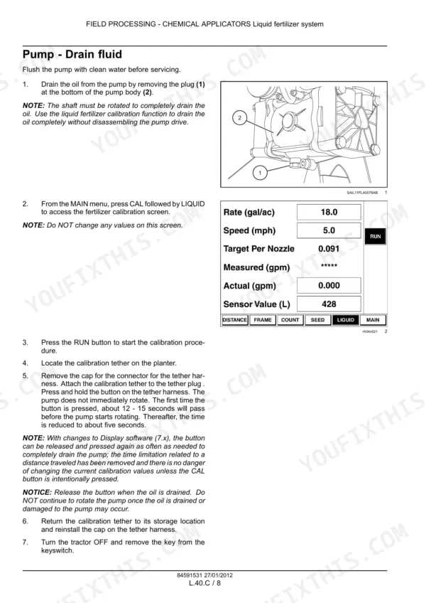
| Chemical Applicators [40.B, 40.C] | 1571-1642 | Granular Chemical Meter, Drive Chain and Clutch, Liquid Fertilizer Pump, Hydraulic Drive Motor, Coulter Bar Cylinder |
| Special Tool Index | 1643-1648 | Special Tools by Fault Code and Procedure |
Quick Reference Specifications
| Specification | Value | Page |
|---|---|---|
| Tractor remote minimum relief pressure | 18616 kPa (2700 psi) | p. 35 |
| 22 US gpm PTO pump output at 1000 RPM | 83.3 - 89.3 L/min (22.0 - 23.6 US gpm) | p. 36 |
| Coulter bar valve block pressure relief setting | 12410 kPa ± 345 kPa (1800 psi ± 50 psi) | p. 41 |
| Pressure relief setting, 24 Row 20 planters | 16892 kPa ± 345 kPa (2450 psi ± 50 psi) | p. 42 |
| Multivalve pressure relief, PTO pump driven valves | 16550 kPa ± 345 kPa (2400 psi ± 50 psi) | p. 45 |
| Outer marker pressure switch, pressure rise setting | 13100 kPa (1900 psi) | p. 91 |
| Vacuum fan motor case drain back pressure, max | 172 kPa (23 psi) | p. 121 |
| Lift and pivot valve solenoid coil nut torque | 4 - 6 Nm (35 - 53 lb in) | p. 37 |
| Lift and pivot valve solenoid valves torque | 47 - 54 Nm (35 - 40 lb ft) | p. 37 |
| AccuRow compressor pressure switch | closes at 85 psi, opens at 105 psi | p. 328 |
| Ground speed sensor to sprocket gap, nominal | 2 mm (0.07 in) | p. 802 |
| Raise solenoid coil resistance | 6 - 9 ohms | p. 1094 |
| Fan flow control solenoid coil resistance | 5 - 12 ohms | p. 1372 |
| Opener disc minimum outside diameter | 343 mm (13.5 in) | p. 1334 |
| Carrying wheel nut torque | 203 - 244 Nm (150 - 180 lb ft) | p. 1068 |