Part of the Case IH Repair Manuals.
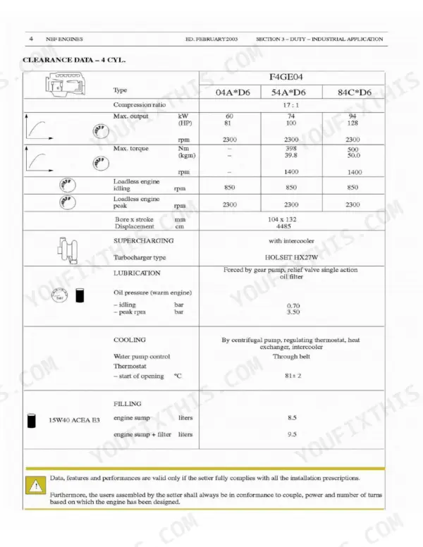
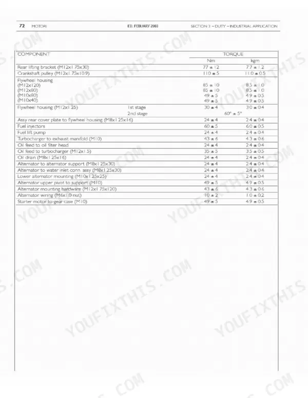
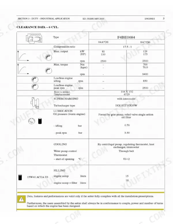
Crankshaft out, bearing caps on the bench, and no torque figures within reach. The Case IH 445/M2, 445T/M2 Repair Manual PDF, 180 pages under OEM number 6-17660, is the factory book for this four cylinder engine. Overhaul is split by feed system, so you follow one path for the mechanical rotary pump and another for the in-line pump unit, each running from engine setting through disassembly to feed system bleed. Cylinder unit, timing system, output shaft, connecting rod and piston, and cylinder head work fill the largest stretch of the book, backed by clearance data, troubleshooting charts and maintenance planning. Set injection pressure at 245 bar on the F4GE0404A*D6 and 260 bar on the rest, check that the thermostat starts opening at 81 ± 2 °C, and pull main bearing caps to 50 ± 6 Nm before the 80 ± 6 Nm second stage. Every hour that engine sits apart costs you. Bookmarked and text searchable, so the section you want is two clicks away.
What's Inside This Repair Manual
| System | Pages | Key Topics |
|---|---|---|
| General Information | 1-22 | Engine Identification Code, Specific Engine Code |
| Feed | 23-34 | Injection Feed System by Mechanical Rotary Pump, Injection Feed System by Mechanical Pump Unit |
| General Information and Mechanical Components | 35-42 | Mechanical Feed Pump, Clearance Data, Mechanical Components |
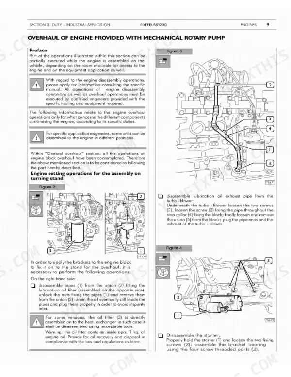
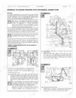
| Overhaul of Engine Provided with Mechanical Rotary Pump | 43-72 | Engine Setting, Disassembly of Application Components, Rotary Feed Pump Disassembly, Feed System Bleed, Power Take-Off |
| Overhaul of Engine Provided with Mechanical In-Line Pump | 73-106 | Engine Setting, Disassembly of Application Components, Feed Pump Unit Disassembly, Feed System Bleed, Power Take-Off |
| Electrical Equipment | 107-116 | Electrical Component Layout, Cooling Liquid Temperature Sensor, Starter, KSB Water Temperature Sensor, Alternator |
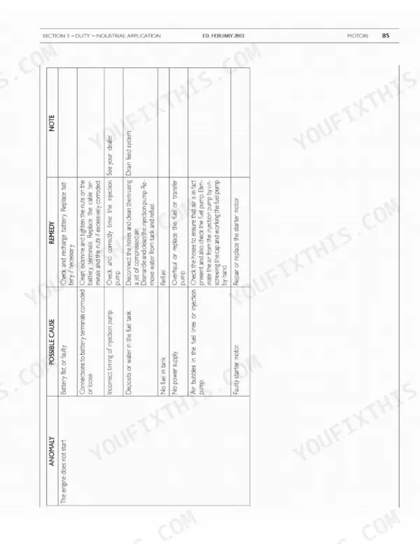
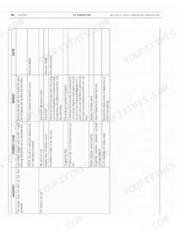
| Troubleshooting and Maintenance Planning | 117-134 | Troubleshooting, Maintenance Planning, Engine Oil Level Check, Fuel System Check, Cooling System Check |
| Overhaul and Technical Specifications | 135-170 | Cylinder Unit, Timing System, Output Shaft, Connecting Rod - Piston Assembly, Cylinder Head |
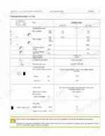
| Equipment | 171-174 | Tools |
| Installation Guidelines | 175-180 | Safety Prescriptions |
Quick Reference Specifications
| Specification | Value | Page |
|---|---|---|
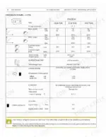
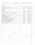
| Thermostat start of opening | 81 ± 2 °C | p. 38 |
| Injection pressure | 245 bar for F4GE0404A*D6, 260 bar for others | p. 137 |
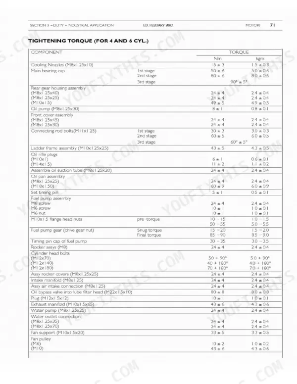
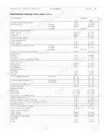
| Main bearing cap torque 1st stage | 50 ± 6 Nm | p. 105 |
| Main bearing cap torque 2nd stage | 80 ± 6 Nm | p. 105 |
| Connecting rod bolts torque 1st stage | 30 ± 3 Nm | p. 105 |
| Connecting rod bolts torque 2nd stage | 60 ± 5 Nm | p. 105 |
| Cylinder head bolts torque (M12x70) | 50 Nm + 90 deg | p. 105 |
| Cylinder head bolts torque (M12x140) | 40 Nm + 180 deg | p. 105 |
| Cylinder head bolts torque (M12x180) | 70 Nm + 180 deg | p. 105 |
| Oil pressure (warm engine) idling | 0.70 bar | p. 38 |
| Oil pressure (warm engine) peak rpm | 3.50 bar | p. 38 |
| Engine sump oil capacity | 8.5 liters | p. 38 |