
Part of the Case IH Repair Manuals.
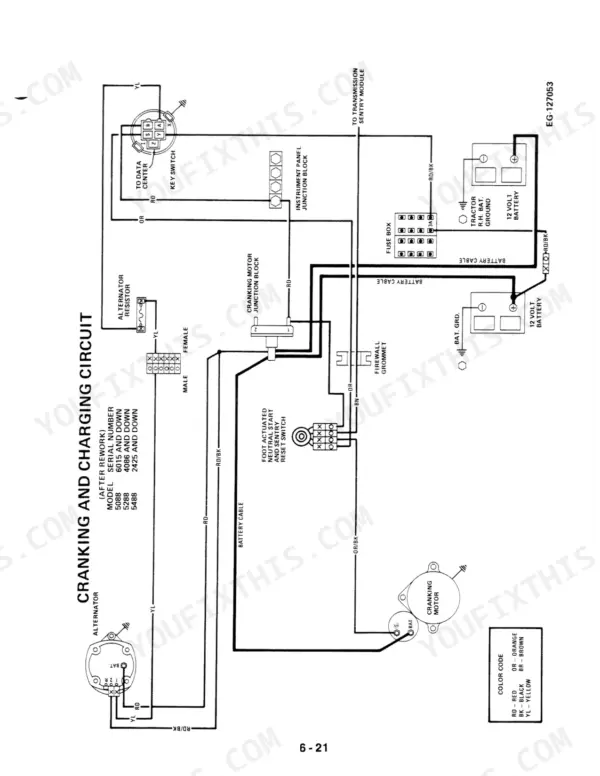
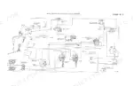
Factory provenance sits on the cover: document GSS-1505-1, 550 pages, the Case IH 5088, 5288, 5488 service manual PDF written for these three row crop tractors. Wiring diagrams follow the Digital Data Center 1A and Sentry System circuits connector by connector, while the hydraulic chapters trace power priority flow through the motor and auxiliary valves. Testing and troubleshooting the hydraulic system fills the back end of the book, pressure checks and symptom tables included. Set the neutral start switch clearance at 38 to 51 mm (1.5 to 2.0 in.); the stop spacer on your 5288 or 5488 measures 34.87 mm (1.372 inches), and master clutch retaining fittings torque to 240 to 270 N·m (177 to 200 ft. lbs.). Bookmarks by system and a searchable text layer open the transmission or rear frame chapter in seconds, so the split closes while the weather still holds.
What's Inside This Case IH 5088, 5288, 5488 Manual
| System | Pages | Key Topics |
|---|---|---|
| Safe Work Rules | 8-9 | Safety Stands, Hydraulic Jacks, Frame Lock Pin, Safety Glasses, Fire Extinguisher, Protective Fixture |
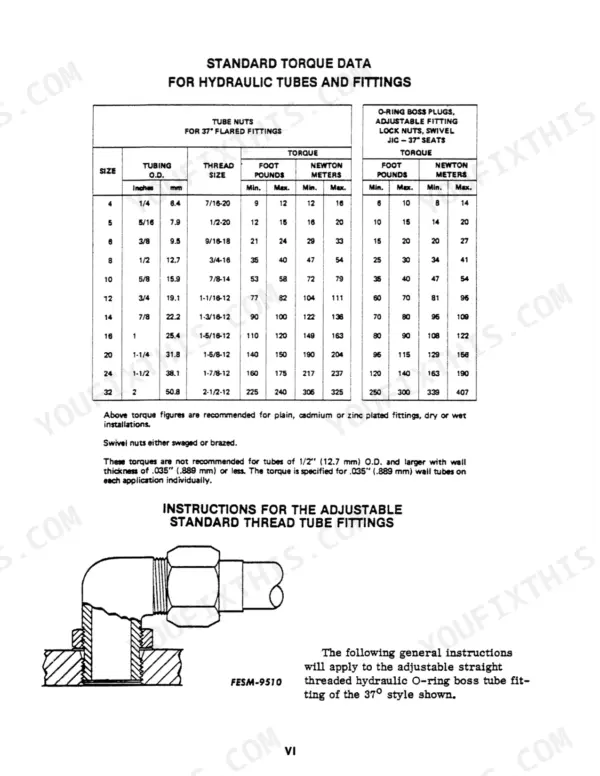
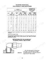
| Standard Torque Data for Hydraulic Tubes and Fittings | 10-11 | Tube Nuts, O-Ring Boss Plugs, Adjustable Fittings, Swivel Nuts, Straight Threaded Fittings |
| Metric Conversion Tables | 12-13 | Inches to Millimeters, Millimeters to Inches |
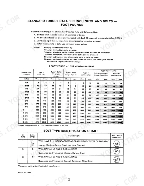
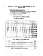
| Standard Torque Data for Nuts and Bolts | 14-16 | Inch Nuts, Inch Bolts, Metric Nuts, Metric Bolts, Bolt Type Identification |
| Special Service Tools Required | 17-22 | Tractor Handler, Rear Frame Handler, Splitting Adapter, Support Assembly, Engine Support Hooks, Adapter Plates |
| Service Information System (S.I.S.) | 23-26 | Film Viewer, Program Cartridge, Training Programs, Service Manuals |
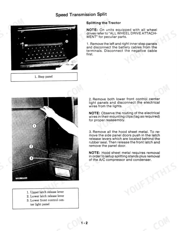
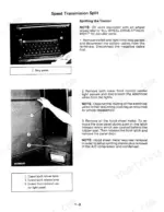
| Tractor Splits | 27-58 | Speed Transmission Split, Range Transmission and Rear Frame Split |
| Front Axle Assembly | 59-130 | Standard Adjustable Front Axle, High Capacity Front Axle, All Wheel Drive Axle |
| Steering | 131-164 | Steering Hand Pump, Power Steering Cylinder |
| Engine | 165-172 | Engine Flywheel Split, Engine Removal |
| Fuel System | 173-176 | Main Fuel Tank, Auxiliary Fuel Tank |
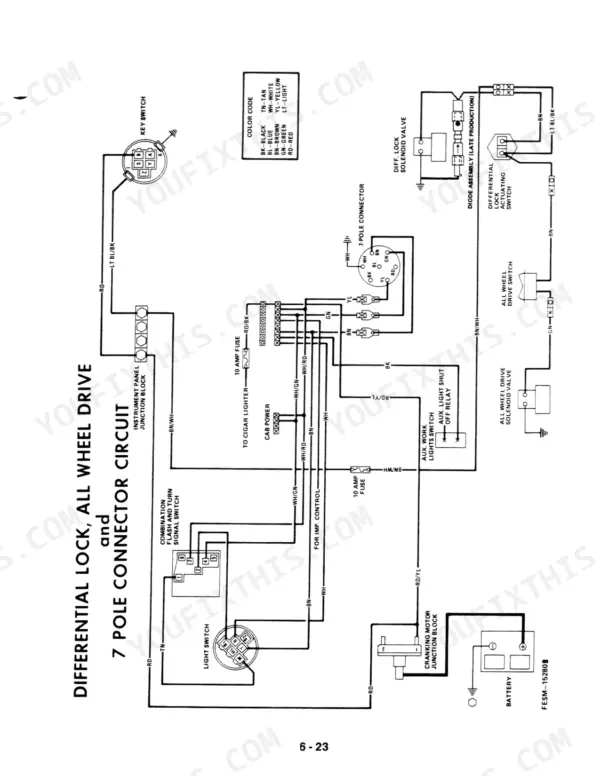
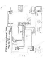
| Electrical System | 177-208 | Digital Data Center 1A, Sentry System, Wiring Diagrams |
| Cooling System | 209-218 | Forward Air Flow, Radiator |
| Master Clutch | 219-226 | Disassembly, Reassembly |
| Transmission | 227-302 | Range Transmission, Speed Transmission Overhaul, All Wheel Drive Clutch |
| Rear Frame Assembly | 303-362 | Differential Assembly, Differential Overhaul in Chassis, Rear Frame Overhaul |
| Rear Axle Assembly | 363-378 | Rear Axle Split, Planetary Assembly |
| Brakes | 379-390 | Brake Valve Service, Brake Pedal and Linkage Adjustment |
| Independent Power Take Off | 391-412 | IPTO Assembly, Dual Speed IPTO Assembly, IPTO Valve Adjustment |
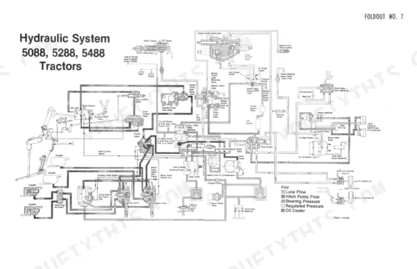
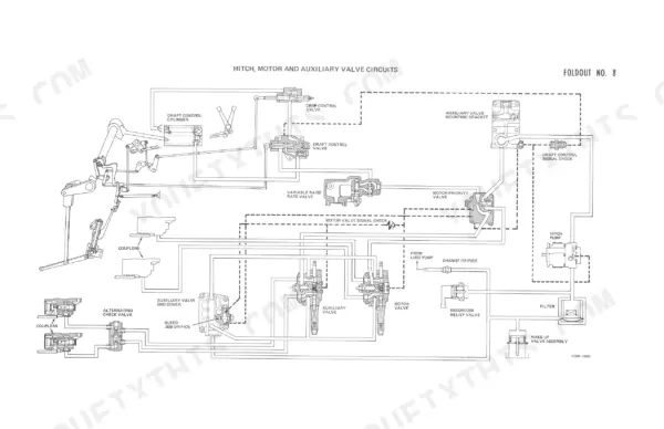
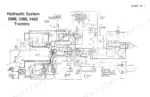
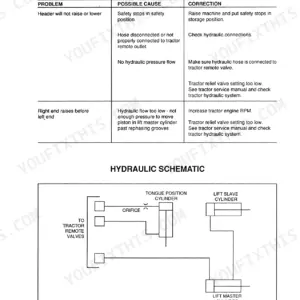
| Hydraulic System | 413-502 | Power Priority Hydraulic System Operation, Motor and Auxiliary Valves |
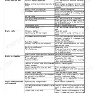
| Testing Hydraulic System | 503-550 | Troubleshooting, Steering/Regulated System |
Quick Reference Specifications
| Specification | Value | Page |
|---|---|---|
| All Models | ||
| Gould Solenoid mounting torque | 20 N·m (180 in-lb) | p. 502 |
| Neutral start switch adjustment clearance | 38-51 mm (1.5-2.0 in.) | p. 208 |
| Master clutch mounting bolts torque | 54 to 61 N·m (39 to 44 ft. lbs.) | p. 224 |
| Master clutch retaining fittings torque | 240 to 270 N·m (177 to 200 ft. lbs.) | p. 225 |
| Stop spacer length (5288 and 5488) | 34.87 mm (1.372 inches) | p. 221 |
| Stop spacer length (5088) | 36.33 mm (1.426 inches) | p. 221 |
| Gould Coil mounting nut torque | 15 N·m (130 in-lb) | p. 502 |
| Hydraulic Pump Cutoff Pressure | 18271 kPa (2650 ± 50 psi) | p. 415 |
| Pressure Regulator Valve (Brakes, Clutches, Seat, AWD, Ipto) | 1585-1930 kPa (230-280 psi) | p. 436 |
| Transmission Lubrication Relief Valve Pressure | 241 to 379 kPa (35 to 55 psi) | p. 506 |
| 5088 | ||
| Steering Relief Valve Pressure (Standard Axle) | 14825 kPa (2150 psi) | p. 436 |
| 5288, 5488 | ||
| Steering Relief Valve Pressure (High Capacity/AWD Axle) | 16890 kPa (2450 psi) | p. 436 |
Case IH 5088, 5288, 5488 Common Problems This Manual Covers
Case IH 5088 transmission slipping under load in high range, hard shifting between gears at high hours
Check transmission lube pressure before pulling anything apart. Pressure should hold 241 to 379 kPa (35 to 55 psi) per the relief valve spec on page 506. If pressure is good, measure clutch pack leakage; anything over 3.7 L/m (1 gpm) on page 275 means the packs are done.
Manual Section: Transmission Troubleshooting p. 516Hydraulic remotes stop working or respond weakly, hitch raises slowly with implement mounted
Warm the oil, then dead-head the pump and read cutoff pressure. It should sit at 18271 kPa (2650 plus or minus 50 psi) as listed on page 415. Trace flow paths on the schematic at page 543 before condemning a valve.
Manual Section: Power Priority Hydraulic (PPH) System Troubleshooting p. 508Differential lock will not engage when pulling in soft ground, pedal goes down with no response
Test the diff lock circuit at the regulator port first. Pressure regulator valve output must fall between 1585 and 1930 kPa (230 to 280 psi) per page 436. If pressure is correct, the problem is electrical: check the switch, the solenoid coil, and the supply line for cracks. Torque a replacement Gould solenoid to 20 N.m (180 in-lb).
Manual Section: Steering/Regulated System Troubleshooting p. 513Cab lights, wipers, and switches dead or intermittent while dash gauges still read normally
Pull the fuse block cover and inspect for melted terminals and heat-browned insulation before chasing individual circuits. Follow the cab feed through the wiring diagram on page 197 and check for voltage drop at each relay and ground. Replace any harness section with discolored insulation. Verify the neutral start switch clearance sits at 38 to 51 mm (1.5 to 2.0 in.) while you are in there.
Manual Section: Electrical System p. 177Master clutch grabs aggressively or will not engage, tractor chatters when starting a load
Split the tractor and measure the stop spacer length before replacing parts. Verify it matches your model spec on page 221, since the 5288 and 5488 use 34.87 mm (1.372 inches). Reassemble with mounting bolts torqued to 54 to 61 N.m (39 to 44 ft. lbs.) and retaining fittings at 240 to 270 N.m (177 to 200 ft. lbs.).
Manual Section: Master Clutch Troubleshooting p. 515Heavy steering effort or slow power steering response, worse at low engine RPM with loader mounted
Check steering pump flow first. Rated output is 45.4 Litres/min (12 gpm) at 10342 kPa (1500 psi) per page 506. Then test the steering relief valve setting listed on page 436 for your axle type and do not mix the standard and high capacity values.
Manual Section: Steering/Regulated System Troubleshooting p. 513Frequently Asked Questions
What are the front wheel hub bolt torque specs on a Case IH 5088, 5288, 5488 standard adjustable front axle?
For the standard adjustable front axle, the front wheel hub bolts should be torqued to between 122 and 170 N-m (90 to 125 ft. lbs.). p. 60
What is the recommended torque for the rear axle carrier bolts on a Case IH 5088, 5288, 5488 tractor?
The rear axle carrier bolts must be torqued to between 233 and 263 N-m (172 to 194 ft. lbs.). p. 373
What is the correct procedure for bleeding the brakes on these tractors?
Attach a hose to the bleeder valve on the rear frame housing and submerge the other end in a container. With the engine idling, push the pedal forward to set the brake, hold it, and loosen the bleeder valve until air bubbles cease to appear. Close the valve securely and repeat if the pedal feels spongy. p. 389
What is the required torque for the IPTO drive gear retaining bolt on a Case IH 5088, 5288, 5488 tractor?
The IPTO drive gear retaining bolt should be torqued to between 90 and 100 N-m (66 to 74 ft. lbs.). p. 322
What is the specified hydraulic seat accumulator pressure on a Case IH 5088, 5288, 5488 tractor?
The accumulator should be charged to 276 to 345 kPa (40 to 50 psi) using compressed shop air. p. 492
How quickly can I access this Case IH 5088 manual after buying?
You get a 550-page searchable PDF that downloads instantly after checkout. Open it on your laptop, tablet, or phone, and bring it right to the shop floor.
Does this Case IH 5088 manual allow printing?
You can. Print the sections you want for your own use and keep the file as your backup.




Reviews
There are no reviews yet.