
Part of the Case IH Repair Manuals.
The continuously variable transmission is the system most owners fear opening up, and Section 21 covers it. It takes you through the CVT external controls, lubrication and internal components. Around it sit the 6.6 litre six-cylinder Tier 3 engine, 4WD, front axle suspension, rear axle, PTO, brakes, hydraulics, steering, cab climate and a full electrical section with DTC tables.
A CVX parked with a warning on the cluster costs you drilling or baling days you will not get back. These 1887 pages cover the CVX140, CVX150, CVX160, CVX175 and CVX195. Torque charts and fluid capacities are at the front of the book.
The book is a PDF, so it goes with the tractor. Put it on the shop laptop, a tablet in the cab or your phone at the field edge.
What's Inside This Case IH CVX140–CVX195 Manual
| System | Pages | Key Topics |
|---|---|---|
| Introduction | 8-27 | Safety, Torque Charts, Standard Torque Data for Hydraulics, Capacities |
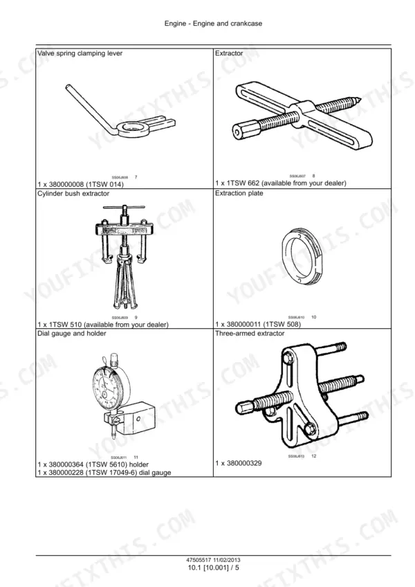
| Engine | 28-173 | Engine and Crankcase, Valve Drive and Gears, Cylinder Heads, Fuel Injection System, Turbocharger, Cooling, Lubrication |
| Transmission | 174-381 | Continuously Variable Transmission (CVT) External Controls, Lubrication System, Internal Components |
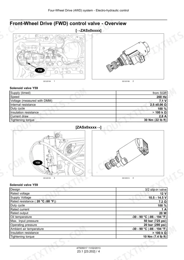
| Four-Wheel Drive (4WD) System | 382-423 | Electro-Hydraulic Control, Drive Shaft |
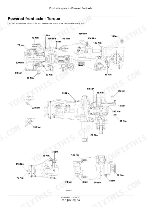
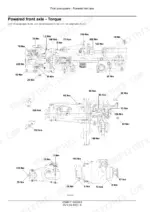
| Front Axle System | 424-633 | Powered Front Axle, Front Bevel Gear Set and Differential, Final Drive Hubs and Steering Knuckles, Axle Suspension Control |
| Rear Axle System | 634-695 | Powered Rear Axle, Rear Bevel Gear Set and Differential, Planetary and Final Drives |
| Power Take-Off (PTO) | 696-765 | Rear Electro-Hydraulic Control, Four-Speed Rear PTO, Front PTO Control, Front PTO |
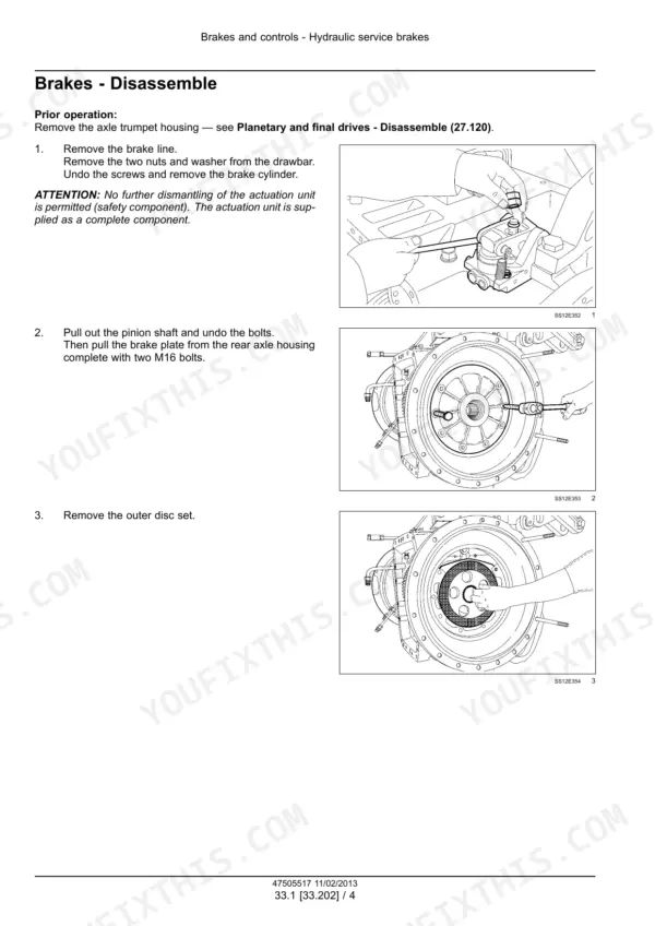
| Brakes and Controls | 766-837 | Hydraulic Service Brakes, Parking Lock, Trailer Brake Hydraulic Control, Front Axle Brake, Brake Cooling |
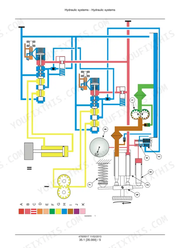
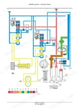
| Hydraulic Systems | 838-951 | Hydraulic Schematics, Variable Displacement Pump, Main Control Valve, Remote Control Valves, Three-Point Hitch |
| Steering | 952-975 | Hydraulic Control Components, Cylinders, Autoguidance Steering |
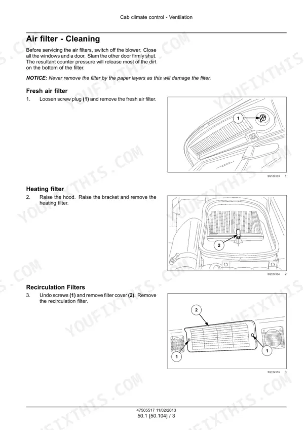
| Cab Climate Control | 976-1033 | Ventilation, Air Conditioning |
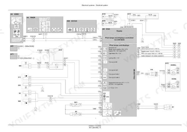
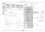
| Electrical Systems | 1034-1077 | Wiring Diagrams |
| Harnesses and Connectors | 1078-1595 | Wiring Diagrams |
| Cab Engine Controls | 1596-1655 | Engine and Transmission Control |
| Electronic Modules | 1656-1679 | Fault Codes (DTC) |
| Cab Transmission Controls | 1680-1727 | Transmission Control System, Transmission Speed Sensors, Transmission Pressure Sensors, Transmission Temperature Sensors, Transmission Position Sensors |
| Front Axle Control System | 1728-1767 | Suspension Position Sensor, Suspension Control, Rear Power Take-Off (PTO) Control System, Front Power Take-Off (PTO) Control System, Air-Conditioning (HVAC) Controls |
| Cab Brake Controls | 1768-1831 | Service Brake Electrical System, Trailer Brake Electrical System, Steering Control System, Rear Three-Point Hitch Electronic Control System, Front Hitch Electronic Control System, Autopilot/Autoguidance |
| Cab or Platform Harnesses and Connectors | 1832-1887 | Instruments |
Quick Reference Specifications
| Specification | Value | Page |
|---|---|---|
| Engine types | 620.60 (CVX140), 620.61 (CVX150), 620.62 (CVX160), 620.63 (CVX175), 620.64 (CVX195); 6 cylinders, 6.6 dm3, Tier 3, turbocharger with charge air cooler | p. 35 |
| Bore x stroke | 108 mm x 120 mm | p. 35 |
| Nominal power at 2100 rpm (ISO 14396) | 104 / 111 / 118 / 129 / 144 kW (141 / 150 / 160 / 175 / 196 HP) for CVX140 / 150 / 160 / 175 / 195 | p. 35 |
| Compression ratio | 18.5 : 1 | p. 36 |
| Injection sequence | 1-5-3-6-2-4 | p. 36 |
| Minimum compression pressure (operating temperature, starter speed) | 24 bar, max. 3 bar difference between cylinders | p. 36 |
| Valve clearance (cold and warm engine) | inlet 0.35 mm, outlet 0.35 mm | p. 64 |
| Cylinder head bolts and nuts | 80 Nm + 90 deg + 90 deg | p. 32 |
| Nut on crankshaft | 1000 Nm | p. 32 |
| Fuel tank capacity | 310 l (82 US gal) | p. 27 |
| Cooling system capacity | 25 l (6.6 US gal) | p. 27 |
| Engine oil capacity including filter | 20 l (5.3 US gal) | p. 27 |
| Transmission / rear axle middle section | approx. 60 l (15.9 US gal) | p. 27 |
| Hydraulic system / steering | approx. 52 l (13.7 US gal) | p. 27 |
| Front wheel nuts before bleeding the braked front axle | 570 Nm | p. 810 |
Case IH CVX140–CVX195 Common Problems This Manual Covers
Low power and poor throttle response on the six-cylinder engine
Check the air filter, intake and exhaust for leaks, fuel feed pressure and fuel quality first. Then suspect the injectors, high-pressure pump, EEM3 control unit or ID module. Finish with a compression test: 24 bar minimum per cylinder, with no more than 3 bar between cylinders.
Manual Section: 10 Engine p. 136Air in the braked front axle after hub or axle work
Fit the front wheels and torque the nuts to 570 Nm. Run the engine and open the vent screw on the steering knuckle housing. Pump the brake until the oil runs out bubble-free, then repeat on the opposite side. Top up the oil and road test before going back to work.
Manual Section: 33 Brakes and controls p. 810Fault FC FMGR 64: tractor won't drive after an FMGR transmission box swap
A used FMGR from a tractor with a different output class will set this fault. Connect the EST, transfer the software to the new box, then calibrate the clutch pedal switch in the Configuration menu. Then test drive, check all functions and read the error memory, fixing any new errors it shows.
Manual Section: 55 Electrical systems p. 1675Refitting a cylinder head and setting the valves correctly
Torque the cylinder head bolts and nuts to 80 Nm, then turn them a further 90 degrees and another 90 degrees. Set inlet and outlet valve clearance to 0.35 mm, which is the same figure cold or warm.
Manual Section: 10 Engine p. 32Frequently Asked Questions
How do I read and clear the error codes stored in the CVX controllers?
The digital instrument cluster shows a list of up to ten error codes for each controller. To clear them, move the arrow to CL and press button 11. That clears the codes from every controller at once, not just the one you are looking at. The DTC tables in the Electrical systems section tell you what each code means. Fix the cause before you clear anything, or the warning will be back on the next start. The Electronic Service Tool (EST) can also read the controllers. p. 1851
Why is the front axle suspension lamp flashing fast with the suspension stuck in one position?
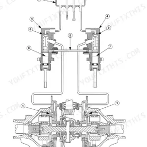
An irregular flash at about 3 Hz means the system is flashing an error code and the valve controller has switched off. Count the flashes between a long pause and a short pause. Code 21, for example, is a long pause, two flashes, a short pause, then one flash. Once the fault is fixed, turn the key switch OFF and back ON to acknowledge it. The full procedure is under axle suspension control in the Front axle system section. p. 615
The engine feels flat and slow to respond, but the turbocharger checks out. Where do I look next?
Work through the cheap items first: a dirty air filter, intake or exhaust leaks, low fuel feed pressure or poor fuel. After that, suspect the injectors, the high-pressure pump, the EEM3 control unit or the ID module. Then do a compression test at operating temperature and starter speed. Each cylinder needs at least 24 bar, and no two cylinders can differ by more than 3 bar. p. 136
Why is the front axle brake spongy after I had the axle apart?
There is air in the front axle brake. Refit the front wheels and torque the wheel nuts to 570 Nm before you bleed. Start the engine and open the vent screw on the steering knuckle housing. Work the brake until oil comes out with no bubbles, then do the other side. Check the oil level and take it for a test run before it goes back on a trailer or a slope. p. 810
I fitted a replacement FMGR transmission box and now the tractor won't move, with fault FC FMGR 64. What's wrong?
The box most likely came off another tractor with a different output class. Use the EST to transfer the software to the new FMGR. Then calibrate the clutch pedal switch in Configuration. Until both steps are done the tractor will not drive, so do them before you start looking for a mechanical fault. p. 1675




Reviews
There are no reviews yet.