Part of the Case IH Repair Manuals.
Pinning down which sensor, connector or valve is at fault on the FLX810 and its Flex-Air variant is the job this 325-page Case IH book settles, catalogued under OEM ID 87269131. Wiring diagrams in this Case IH FLX810 diagnostic manual PDF trace the Surveyor cab, SCS 4600 and Viper electrical systems, with component tests for the granular, wet kit and foamer circuits. Hydraulic schematics map the multifunction valves and metering circuit, while the controller section takes you through calibration and the SCS 4600 and Viper troubleshooting guides. Set the blower RPM magnetic sensor gap at 1/8 to 1/4 inch, then torque a -6 O-ring face seal end to 216 to 240 pound-inches. Chasing an electrical fault in your Surveyor cab wiring? The connector testing pages narrow it down. Bought once, the bookmarked, text-searchable file stays yours for this machine, ready whenever the Viper or SCS 4600 system needs another look.
What's Inside This Case IH FLX810 Flex-Air Manual
| System | Pages | Key Topics |
|---|---|---|
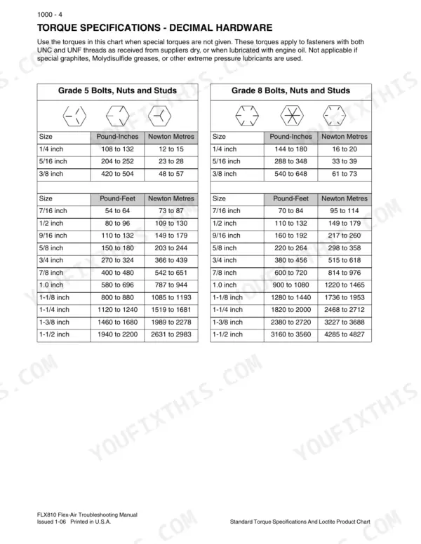
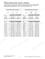
| Standard Torque Specifications | 6-15 | Torque Specifications - Decimal Hardware (Grade: 5 Bolts, Nuts and Studs, Bolts, Nuts and Studs) |
| Safety | 16-29 | Personal Safety, Safety Rules |
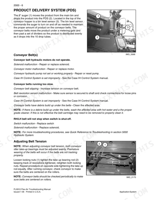
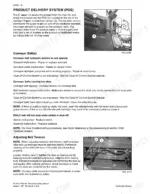
| Application System | 30-53 | Augers, Product Delivery System, Foam Marker System, Wet Kit |
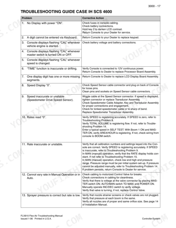
| Controller System | 54-87 | Calibration Procedure, Troubleshooting Guide Case IH SCS 4600, Troubleshooting Guide Case IH Viper |
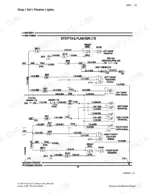
| Electrical System | 88-107 | Electrical System Diagnostics, Troubleshooting Procedures, Troubleshooting Tests |
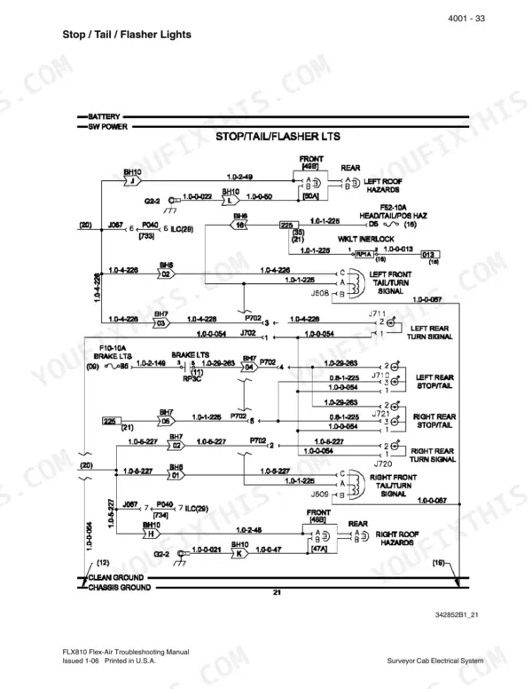
| Surveyor Cab Electrical System | 108-155 | Connector Testing |
| Case IH SCS 4600 Electrical System | 156-211 | Granular Component Testing, Wet Kit Component Testing |
| Case IH Viper Electrical System | 212-277 | Granular Component Testing, Foamer Component Testing |
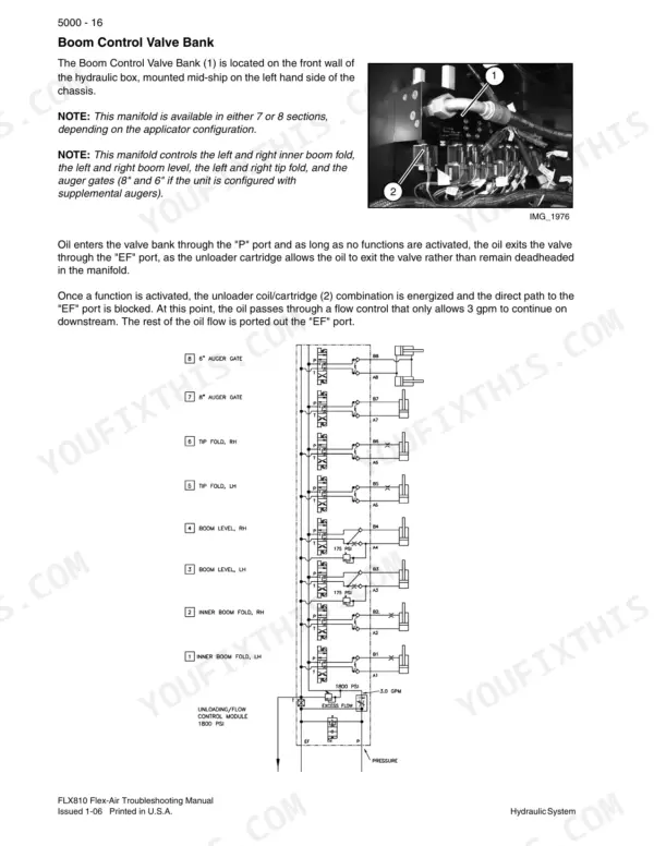
| Hydraulic System | 278-309 | Multifunction Valves, Metering Circuit |
| Flex-Air Required and Recommended Tool List | 310-325 | Required Tools, Recommended Tools |
Quick Reference Specifications
| Specification | Value | Page |
|---|---|---|
| 37 Degree Flare Fitting Torque (1/4 inch Tube OD) | 72 to 144 Pound-Inches | p. 11 |
| 37 Degree Flare Fitting Torque (5/16 inch Tube OD) | 96 to 192 Pound-Inches | p. 11 |
| O-Ring Face Seal End Torque (-4 Dash Size) | 120 to 144 Pound-Inches | p. 12 |
| O-Ring Face Seal End Torque (-6 Dash Size) | 216 to 240 Pound-Inches | p. 12 |
| Blower RPM magnetic sensor spacing | 1/8 inch to 1/4 inch | p. 9 |
| Fan RPM Sensor Voltage | + 12V | p. 169 |
| Main Auger RPM | 1600 RPM | p. 34 |
| Blower Rotor Max RPM | 6000 RPM | p. 38 |
| System Hydraulic Pressure (Blowers) | 2400 PSI | p. 38 |
| Pressure Washer Pump Oil Change Interval | 200 hours | p. 46 |
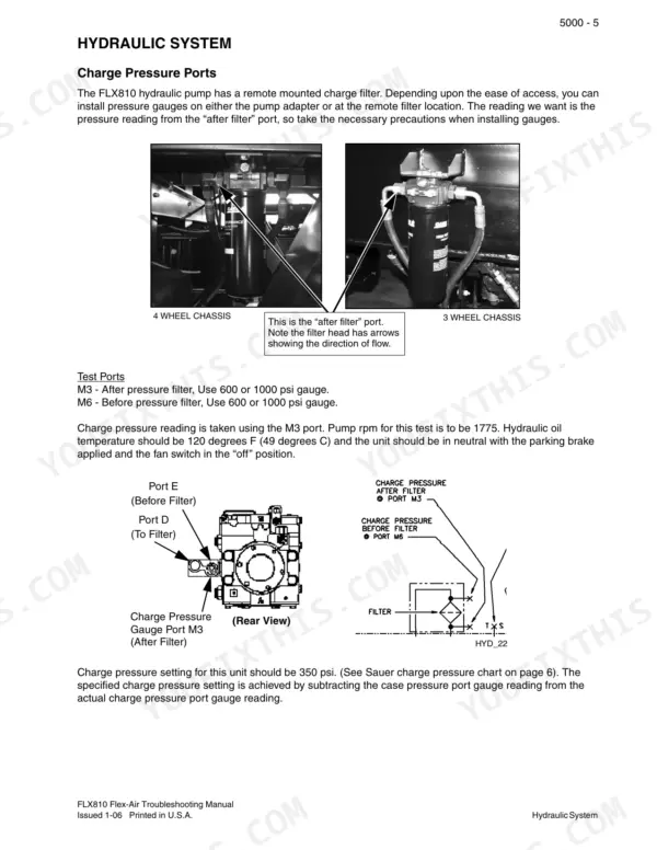
| Charge Pressure Setting | 350 PSI | p. 282 |
| Maximum Allowable Continuous Case Pressure | 44 PSI | p. 285 |
Case IH FLX810 Flex-Air Common Problems This Manual Covers
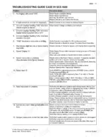
Case IH FLX810 Flex-Air fan RPM sensor reading erratic or dropping to zero on SCS 4600 display
Test the fan RPM sensor circuit following the SCS 4600 granular component testing on page 169. Measure sensor supply with the key on and confirm +12V. If supply is missing, run the power distribution and circuit troubleshooting tests in the Electrical System Diagnostics section. A displayed blower speed above the 6000 RPM rotor maximum on page 38 points to a bad signal.
Manual Section: Case IH SCS 4600 Electrical System p. 169Blower speed will not climb to target RPM with blower hydraulics engaged
Check system hydraulic pressure to the blowers against 2400 PSI, listed on page 38. Then verify the electric remote pressure limiter is working within its 3000-6000 rpm operating range on page 289. Run the hydraulic checks exactly as written; page 19 warns not to change the procedure. Before spinning the blowers, clear everyone away from open manifold and boom ports, since discharged material can injure (page 21).
Manual Section: Hydraulic System Diagnostics p. 289Hydraulic charge pressure reading below specification during hydraulic system diagnostic pressure checks
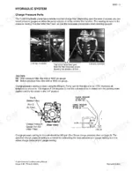
Measure charge pressure and compare it to the 350 PSI setting shown with the hydraulic schematic on page 282. If charge is low, check case pressure next: 44 PSI is the maximum continuous and 73 PSI the maximum intermittent allowed, per page 285. Relieve all pressure before disconnecting any line to install gauges, and never feel for a leak with your hand (page 20).
Manual Section: Hydraulic System Diagnostics p. 282Metering circuit hydraulic pressure low or unstable while applying granular product through the boom
Check the metering circuit relief valve against its 2175 psi setting on page 298. Inspect the in-line pressure filter at the same time; its bypass check valve opens at a 50 psi pressure difference, so look for a restricted element. Follow the metering circuit checks exactly as written (page 19) and relieve all pressure before breaking any connection (page 20).
Manual Section: Hydraulic System Diagnostics p. 298Controller displays No Differential warning or GPS coverage message when starting a job
Enable the differential correction function in the GPS receiver; without it, features such as guidance stay disabled, per the controller messages on page 79. For a non-VRC job, verify GPS signal before starting, since page 78 shows the controller requires coverage. If the receiver will not take correction, contact the receiver manufacturer as the manual directs.
Manual Section: Controller System Troubleshooting p. 79Load sense gear pump flow or pressure low at the boom control valve bank
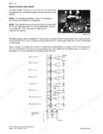
Measure load sense gear pump output against 15-17 gpm and confirm its relief valve holds 2500 psi, both on page 292. Then check the boom control valve bank relief, which should be set at 1800 psi per page 294. When cycling hydraulic cylinders to check operation, make sure all people are out of the way, as page 19 requires.
Manual Section: Hydraulic System Diagnostics p. 292Frequently Asked Questions
What are the torque specifications for a 1/2 inch Grade 5 bolt on the Case IH FLX810 Flex-Air?
For a 1/2 inch Grade 5 bolt, the torque specification is 80 to 96 pound-feet (109 to 130 Newton Metres). p. 9
What is the recommended belt tension for the conveyor belt?
The conveyor belt should have a 3/4 inch deflection measured between the bottom of the conveyor and the belt. Do not over tighten the conveyor belts. p. 36
What is the procedure to check the flow meter cable?
To check the cable, enter a METER CAL number of 1, place BOOM switches to ON, and short between pin 2 and pin 1 with a jumper wire. The TOTAL VOLUME should increase by increments of 1 or more counts each time contact is made. If it does not increase, check the cable for breaks or shorts. p. 82
What is the maximum transport speed for the machine?
The maximum transport speed for the machine is 30 mph (48 km/h). Exceeding this speed may cause loss of control and result in serious injury or death. p. 21
What is the relief valve pressure setting for the auger hydraulic circuit on the Case IH FLX810 Flex-Air?
The auger hydraulic circuit is protected by a relief valve, R2, which has a pressure setting of 2700 psi. p. 296
Is this Case IH FLX810 Diagnostic Manual a digital download?
Delivery is instant: a 325-page searchable PDF is yours the second checkout clears. Laptop, tablet, or phone, all fine.
Can I print specific sections of this Case IH FLX810 Diagnostic Manual?
Yes. Print a chapter or just the pages for the job at hand, for use in your own shop. Any home or office printer works.