
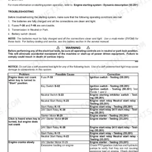

Part of the Case IH Repair Manuals.
Book 2 is the hydraulic volume of the Patriot 3230 and 3330 manual. It covers hydrostatic pump tests, the neutral shunt valve, the park brake circuit, the PWM product pump control valve and troubleshooting charts for the drive, product pump and cylinder circuits. The job stalls when your gauge is teed into the Fa port and you have no spec to read it against. Page 350 gives it: 27 to 29 bar (400 to 420 PSI) at high idle, with the oil at 49 C.
Book 1 carries the specs, maintenance intervals, electrical diagnostics, CAN bus layouts and the Section 4000 engine fault code table. Book 3 covers A/C and ATC codes, the cab, hubs, brakes, booms up to 120 ft and the product pump. The hydraulic and electrical schematics are bound in as fold-outs.
Engine overhaul is not in this manual. It covers engine removal, installation and the isolator mount, and refers you to NEF 6.7L engine manual 84202702 for repairs. The weather sets the spray window, so it helps to have the numbers on the bench before the job starts.
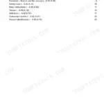
What's Inside This Case IH Patriot 3230, 3330 Manual
| System | Pages | Key Topics |
|---|---|---|
| Master Contents and Standard Torque | 1-18 | Complete Manual Contents for Books 1-3, U.S. Hardware Torque Specifications, Metric Hardware Torque Specifications, Steel Hydraulic Fitting Torques |
| Safety, Lubrication and Maintenance | 19-48 | Precautionary Statements and Safety Rules, Special Tools, Recommended Break-In Maintenance, Lubrication and Preventive Maintenance Schedule, Product Tank and Cab Cleaning, Brake Operation Check, Gear Increaser and Hub Lubricant Checks, Fuel Water Drains, Serpentine and Compressor Belt Replacement |
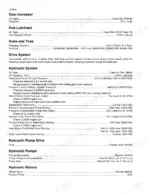
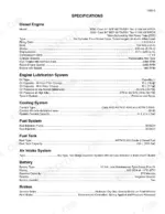
| Specifications and Towing | 49-68 | Diesel Engine Data by Model, Engine Lubrication and Cooling, Fuel Tank, Battery, Gear Increaser and Hub Lubricant, Hydraulic System Pressures and Flows, Pumps and Motors, Suspension, Steering, Travel Speed, Dimensions, Operating Weight, Engine Oil and Coolant, Tire Inflation by Tire Size, Towing Preparation with Park Brake Release by Hand Pump and Pump Bypass, Returning to Service After Towing |
| Engine, Air Induction and Fuel System | 69-122 | Engine Special Torques and Tools, Engine Removal and Installation, Engine Isolator Mount, Air Filter Elements and Restriction Indicator Switch, Intake Air Duct, Fuel System Overview, Fuel Tank Removal and Installation |
| Electrical Diagnostics, Fuses and Controllers | 123-175 | Electrical Special Tools and Symbols, Power Distribution Diagnostics, Basic Troubleshooting, Fuse and Relay Identification, Instrumentation and Controls, Cab Bulkhead Connectors, Ground Points, Controller and Node Locations, Propel System, Vehicle, Application and Autoguidance CAN Bus, Autofold Boom Position Sensors |
| Chassis, Cab and Application Connectors | 176-247 | Chassis and Cab Connector Information, Application System Connector Information |
| Charging, Starting and Engine Fault Codes | 248-266 | Charging System, Starting System, Engine Fault Code Table |
| Battery, Steering Pump and Steering Column | 267-302 | Battery Specifications, Access, Removal and Maintenance, Steering Hand Pump Removal and Installation, Steering Column and Center Console Assembly |
| Book 2 Hydraulics: Reading Schematics | 303-332 | Book 2 Contents, How to Read Symbols in a Hydraulic Schematic, Simple Schematic, Common Symbols |
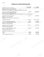
| Hydraulic System Troubleshooting | 333-402 | Hydraulic Special Torques and System Specifications, Drive, Product Pump and Cylinder Circuit Troubleshooting Charts, Hydrostatic Pump Tests, Wheel Motor, Neutral Shunt Valve, Active Suspension, Parking Brake System, Gear Pump, PWM Product Pump Control Valve, Pressure Compensated Pump, Valve Banks, Steering, Service Brake, Boom Cylinder Tests |
| Hydraulic Tank, Filters and Pumps | 403-454 | Hydraulic Filters, Hydraulic Maintenance Schedule, Tank Draining and Filling, Hydraulic Tank, Gear Pump, Pressure Compensated Pump, Hydrostatic Pump |
| Product Pump Motor, Wheel Motor and Pump Drive | 455-490 | Product Pump Hydraulic Motor, Wheel Motor Removal and Installation, Pump Drive Removal, Disassembly, Assembly and Installation |
| Hydraulic Valves | 491-538 | Product Pump Control (PWM) Valve, Neutral Shunt Valve, Motor Control Valve, Park Brake Valve, Two Section Valve Bank, Boom Valve Bank, Solenoid Function Test, Manifold, Service Brake Valve |
| Hydraulic Cylinders | 539-574 | Axle Adjust Cylinder, Inner and Outer Boom Fold Cylinders, Boom Height and Boom Level Cylinders, Ladder Cylinder, Active Suspension Cylinder, Steering Cylinder, Cylinder Overhaul |
| A/C Troubleshooting and ATC Fault Codes | 575-664 | Book 3 Contents, A/C Thermal Operation and Components, Automatic Temperature Control Operation, ATC Fault Codes, Locating Problems Without Fault Codes, ATC Controller Test, Compressor Clutch, Pressure Switch Latching Circuit, Heater Valve, Blowers and Temperature Sensors, Standard a/C Troubleshooting |
| Air Conditioner System Service | 665-770 | Refrigerant Recovery, Evacuation and Recharging, Temperature/Pressure Chart, Leak Detection, A/C System Flushing, Compressor Clutch, Condenser, Receiver/Drier, Thermal Expansion Valve Testing and Replacement, Blower Motor |
| Cab, Hoods, Radiator and Coolers | 771-836 | Cab Removal and Installation, Front and Engine Hoods, Cooling Package Cleaning, Air-To-Air Cooler, A/C Condenser, Hydraulic Oil Cooler, Radiator Assembly |
| Wheels, Hubs, Suspension, Brakes and Axles | 837-898 | Tire Inflation, Wheels, Planetary Gear Hub Roll, Leak and Brake Testing, Springs, Trailing Link, Suspension and Steering Arms, Brake Caliper, Brake Bleeding, Front and Rear Axles and Liners |
| Booms | 899-966 | Breakaway Tip, Outer Boom 60, 90, 100 and 120 Ft, Inner and Mid Boom, Cradled Boom Removal, Center Section, Mast, Boom Pivot |
| Product Pump, Reload Station, Valves and Spray Bar | 967-1012 | Product Pump Removal, Disassembly and Installation, Reload Station, Boom Selection Shut Off Valve, Sparge Valve, Spray Nozzles and Spray Bar, Foam Marker Tank, Mixing Chamber and Air Tank |
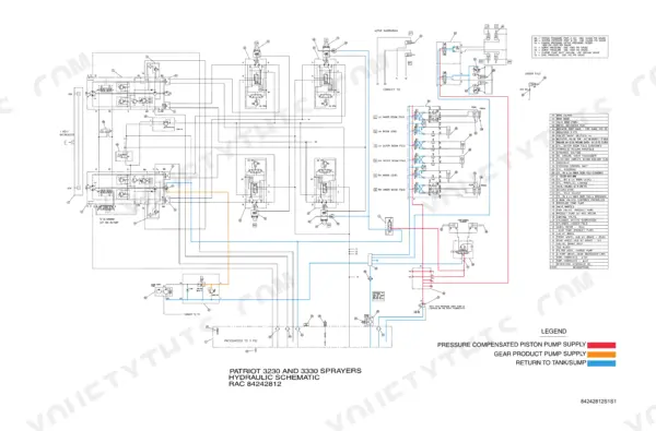
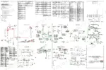
| Hydraulic Schematic | 1013-1014 | Patriot 3230 and 3330 Hydraulic Schematic RAC 84242812 |
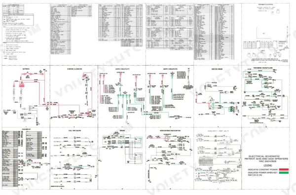
| Electrical Schematic | 1015-1018 | Patriot 3230 and 3330 Electrical Schematic RAC 84242809, Power Train Control Module and Engine ECU Sheets |
Quick Reference Specifications
| Specification | Value | Page |
|---|---|---|
| Engine (3230) | NEF 667TA/EBY Tier III 164 kW HPCR | p. 51 |
| Engine (3330) | NEF 667TA/EB1 Tier III 186 kW HPCR | p. 51 |
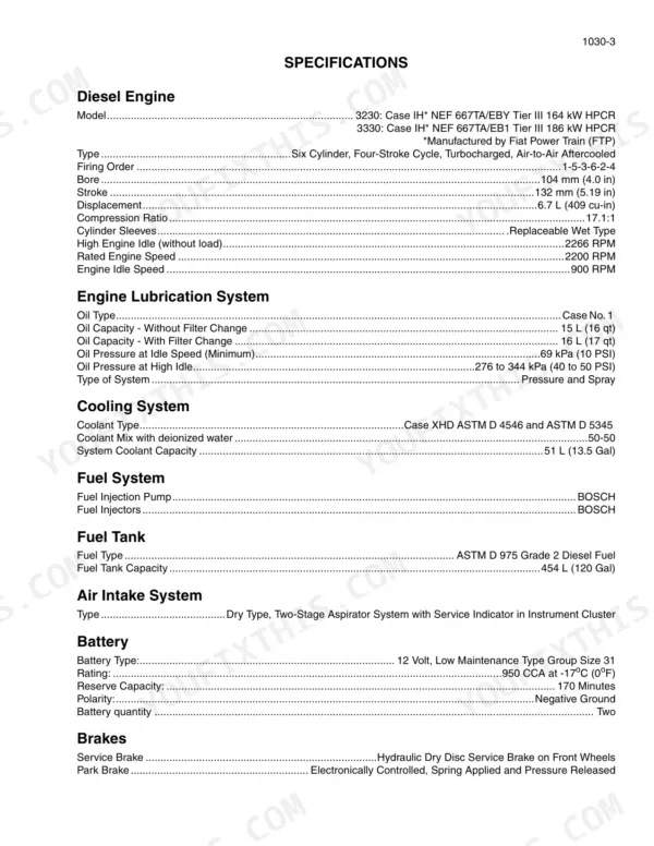
| Displacement | 6.7 L (409 cu-in) | p. 51 |
| Rated engine speed | 2200 RPM | p. 51 |
| Engine oil capacity with filter change | 16 L (17 qt) | p. 51 |
| Cooling system capacity | 51 L (13.5 Gal) | p. 51 |
| Fuel tank capacity | 454 L (120 Gal) | p. 51 |
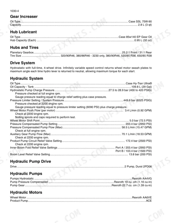
| Hydraulic tank capacity | 109.8 L (29 Gal), Case Hy-Tran Ultra | p. 52 |
| Hub lubricant (each hub) | 0.95 L (32 oz), Case 85w140 EP Gear Oil | p. 52 |
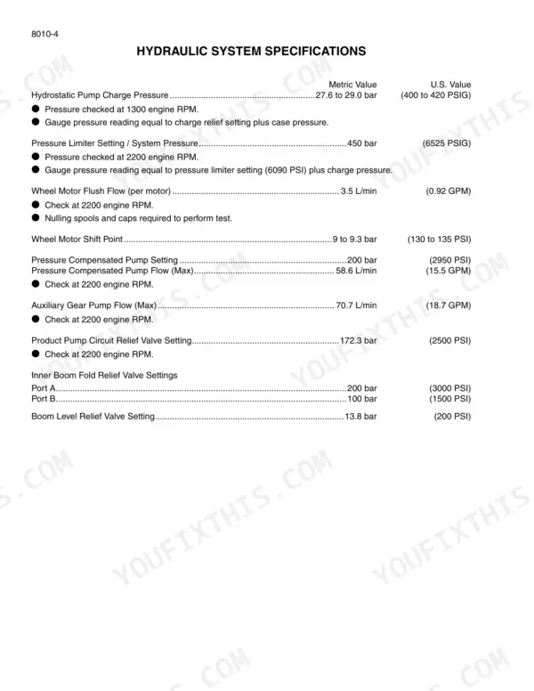
| Hydrostatic charge pressure at high idle | 27 to 29 bar (400 to 420 PSI) | p. 350 |
| Pressure limiter setting / system pressure | 449.8 bar (6525 PSIG) | p. 52 |
| Pressure compensated pump setting | 203.4 bar (2950 PSI) | p. 52 |
| Product pump circuit relief valve | 172.4 bar (2500 PSI) | p. 52 |
| Boom level relief valve | 13.8 bar (200 PSI) | p. 52 |
| Product tank | 3028 L (800 Gal) (3230) / 3785 L (1000 Gal) (3330) | p. 53 |
| Rinse tank capacity | 424 L (112 Gal) | p. 53 |
| Maximum travel speed | 48 km/h (30 mph) | p. 53 |
| A/C refrigerant | HFC 134, 1.65 kg (3.63 lb) | p. 53 |
| Maximum operating weight | 16,392 kg (36,140 lb) | p. 54 |
Case IH Patriot 3230, 3330 Common Problems This Manual Covers
Machine will not move with the engine running
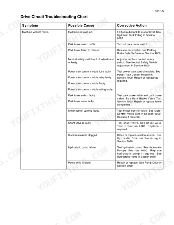
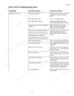
Work down the Drive Circuit Troubleshooting Chart on page 337, starting with oil level, the park brake switch and the neutral safety switch adjustment. The park brake quick disconnect on page 366 is a test aid only, and you should disconnect it only with the engine OFF. With it disconnected, no charge oil reaches the hubs and the spring-applied parking brakes stay applied.
Manual Section: Hydraulic System Troubleshooting - Drive Circuit Troubleshooting Chart p. 337Drive is sluggish or erratic under load
Run the Section 8010 charge pressure test on page 350 with the oil warmed to 49 C and the throttle at high idle. Look for 27 to 29 bar at the Fa port. Each 1 mm relief shim changes pressure by 4 bar (56.5 PSI). Next, run the pressure balance test on page 351. Both pumps must rise together within 35 bar (500 PSI) while a helper holds the service brakes.
Manual Section: Section 8010 Hydrostatic Pump Charge Pressure Test and Pressure Balance Test p. 350Rate controller shows no product pressure at the booms
Page 341 has you set the rate controller to MAN first to rule it out. Then confirm the manual shut-off valves are open and check the hydraulic oil and product tank levels. After that, check the PWM valve driver and the Pump ON sensor. If those are good, move to the product pump/motor in Section 11020 and the gear pump in Section 8040. The circuit relief is 172.4 bar (2500 PSI) at 2200 rpm (page 52).
Manual Section: Product Pump Circuit Troubleshooting Chart, Sections 11020 and 8040 p. 341A/C compressor clutch drops out and stays off
Watch the Instrument Cluster for a code alternating with the cab setpoint, because ATC codes are not stored. Code 129 is high pressure switch cycling, twice in one minute, on page 603. Code 134 is the low pressure switch open for over a minute, on page 605. Once the cause is found, toggle the keyswitch or the ATC switch to re-enable the clutch (page 597).
Manual Section: A/C Troubleshooting and ATC Fault Codes - Pressure Switch Latching Circuit p. 603Frequently Asked Questions
How do I clear or reset fault codes on a Patriot 3230 / 3330?
The manual lists engine codes in the Section 4000 table on page 258, but it gives no procedure for clearing them. The only reset it covers is on the ATC side. Codes 129 and 134 latch the compressor clutch OFF. To bring it back, turn the keyswitch OFF and ON, or switch the ATC OFF and then to A or snowflake (page 597). p. 597
What do the fault codes mean on a Case IH Patriot 3230 or 3330?
Engine codes are four-digit numbers from 3000 up. Each is flagged Amber Warning or Red Stop, for example 3001 Foot Throttle Sensor - Signal Not Plausible and 3028 Oil Pressure Sensor - Pressure Too Low (page 258). ATC codes appear on the Instrument Cluster, alternating with the cab temperature setpoint. They are not stored, so write the code down while it is showing. Code 129 is covered on page 603 and code 134 on page 605. p. 258
Where are the torque specs for the Patriot 3230 / 3330?
U.S. and metric hardware torques and steel hydraulic fitting torques are at the front of Book 1, next to the master contents. The hydraulic special torques are on page 335. The product control valve solenoid takes 128.8 to 135.6 Nm (95 to 100 lb ft). Its relief valve takes 50.2 Nm (37 lb ft) and the charge pressure lock nut takes 52 Nm (39 lb ft). p. 335
Patriot 3230 or 3330 will not move or drives erratically - where do I start?
Check the hydraulic oil level first, because both drive charts list it. For a machine that will not move, page 337 continues with the park brake switch, park brake release, neutral safety switch, power train control module circuit, motor control valve, shunt valve and suction strainers. For sluggish or erratic drive, page 339 adds clogged filters, charge pressure, hub oil level and the Section 9050 hub roll test. p. 337
How do I tow a Patriot 3230 or 3330 with a dead engine or hydrostat?
If the engine or hydrostat is down, the park brake switch will not release the brakes. Kit BN325022 is required and towing speed is limited to 4.8 to 6.4 km/h (3 to 4 mph) (page 64). Hand pump kit BN324972 pressurizes the brake line to 27.6 bar (400 PSI) (page 65). Page 66 covers opening both hydrostatic pump bypass screws six turns with the engine shut down. p. 64





Reviews
There are no reviews yet.