

Part of the Case IH Repair Manuals.
Within the hour you could be under a Titan floater, putting a meter on a DEF level sensor or caging a rear spring brake so the shoes come off.
This book (part number 84559771, January 2012) covers the 3 wheel Titan 3030 and 3530 and the 4 wheel Titan 4030 and 4530. Chapters run from capacities and hydraulics through SCR aftertreatment, the Allison 3000 RDS transmission, Hi-Lo unit, axles, pneumatic brakes, cab and fold-out schematics. The fault code sections give the cause, failure modes and solution steps for each code. The Cursor 8.7 l engine is covered for removal and installation only.
Print the chapter you need and take it to the bench. A torque table with hydraulic oil on it still reads fine.
What's Inside This Case IH Titan 3030, 3530, 4030, 4530 Manual
| System | Pages | Key Topics |
|---|---|---|
| Introduction, Standard Torques, Capacities and Specifications | 1-19 | Safety Rules, Standard Torques for Metric Bolts, Hydraulic Fittings and Split Flanges, Capacities for 3 Wheel (Titan 3030, 3530) and 4 Wheel (Titan 4030, 4530) Models, General Specification by Model |
| Primary Hydraulic Power System | 20-72 | Hydraulic Pump Torque, Hydraulic Symbols, Gear Pump with Load Sensing Priority Flow Divider, Reservoir and Oil Cooler Dynamic Description, Gear Pump and PFC Pump Removal and Installation, Reservoir Fluid and Filter Replacement, Oil Cooler Removal and Installation |
| Pneumatic System | 73-82 | Chassis Pneumatics Dynamic Description: Compressor, Air Tanks, Air Dryer, System Relief Valve, Air Horn, Two Speed Axle Valve and Auxiliary Transmission Valve Locations |
| Electrical Power System, Fuses and Connectors | 83-115 | Fuse and Relay Box Component Identification for 3 and 4 Wheel Models, Battery Switch, 150 Amp Circuit Breaker, Chassis Connector Identification |
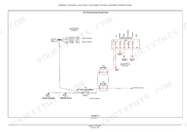
| Wiring Schematic Frames 01-35 (Cab and Power) | 116-181 | Electrical Schematic Frames: Color and Harness Codes, Batteries and Distribution, Cab Power and Fuse Frames, Roof and Work Lights, Turn Signal Module, AC Modules, ICU2, Front Dash, Vehicle, Application and AG CAN Busses, Transmission Circuits |
| Wiring Schematic Frames 36-139 (Chassis, Engine, Auto Guidance) | 182-252 | Electrical Schematic Frames: 3 Wheel and 4 Wheel Main Frame Interface, Radar and Hydraulic Circuits, Lights, Park Brake and Auxiliary Drive, Engine Interface, FPT Engine Externals, ECU and EVGT, DCU Circuits, Auto Guidance NAV, Steer Relays and Raven Interface |
| Fault Codes: Automatic Temperature Control (111-134) | 253-277 | ATC Controller Fault Codes 111-134: Cab and Evaporator Temperature Sensors, Blower and Temperature Selector Potentiometers, High and Low Pressure Switch Faults, With Cause, Failure Modes and Solution Steps |
| Fault Codes: DEF/SCR Aftertreatment (19001-19748) | 278-356 | Denox Supply Module Fault Codes with P-Codes: Battery Voltage, Catalyst Temperature Sensors, Urea Pressure Sensor, Tube Heaters, Dosing Valve, Urea Pump, Urea Tank Level and Temperature, Defreezing, CAN Frames |
| Fault Codes: Engine Control Unit (3001-3612) | 357-571 | Engine ECU Fault Codes: Foot Throttle and Temperature Sensors, Rail and Boost Pressure, Injectors, High Pressure Test, SCR Dosing Valve Protection, Catalyst Efficiency and NOx, Fault Code Index |
| Engine Removal and Installation | 572-618 | Engine Torque and Special Tools, Engine Removal and Installation for 3 Wheel and 4 Wheel Models |
| Fuel Throttle and Air Intake | 619-634 | Foot Throttle Potentiometer Calibration, Air to Air Cooler Removal and Installation on 4 Wheel Models |
| Exhaust Emissions Control (SCR) | 635-706 | SCR Supply Module, Supply Module and In-Line Filter Replacement, Coolant Control Valve, Power Converter, SCR Muffler, Heater/Sensor Assembly, Pre- and Post-Catalyst Temperature Sensors, NOx, Dosing and Humidity Sensors |
| Engine Cooling and Starting System | 707-763 | Cooling System Assembly with Air to Air Cooler and Air Conditioning Condenser Removal, Disassembly and Installation, Radiator Removal and Installation, Grid Heater Cold Start Aid |
| Transmission (Allison 3000 RDS) | 764-790 | Transmission Torque and Special Tools, Transmission Removal and Installation for 3 Wheel and 4 Wheel Models |
| Auxiliary Transmission (Mechanical Hi-Lo Unit) | 791-849 | Hi-Lo Unit Torque, Removal, Disassembly, Assembly and Installation, Drive Shaft to Rear Axle Removal and Installation |
| Front Axle | 850-902 | Front Axle Torque and Special Tools, Bearing Replacement, Removal, Disassembly and Assembly on 3 Wheel Models, Axle, Wheel Hub and Steering Knuckle Service on 4 Wheel Models, Wheel Alignment, Knuckle Vertical End Play, King Pin Bushings, Toe-In Adjustment |
| Rear Axle, Final Drive and Differential | 903-948 | Rear Axle, Final Drive and Differential Torque, Differential Shimming, Rear Axle Removal and Installation, Final Drive Removal, Assembly and Installation, Differential Disassembly and Assembly |
| Steering | 949-972 | Front Steering Fork Torque, Removal and Installation on 3 Wheel Models, Steering Orbital and Steering Cylinder Component Identification |
| Service Brakes (Pneumatic) | 973-1017 | Brake Torque, Pneumatic Brake Dynamic Description, Front Brake Pads, Rotor and Caliper on 3 Wheel Models, Front Brake Shoes on 4 Wheel Models, Rear Axle Brake Removal, Brake Shoe Replacement and Installation |
| Frame and Engine Hood | 1018-1046 | Primary Frame Raise Procedures, Engine Hood Torque, Special Tools, Removal and Installation for 3 Wheel and 4 Wheel Models |
| Cab and Air Conditioning Condenser | 1047-1081 | Cab Mount Torque, Cab Lifting Bracket, Cab Removal and Installation on 3 Wheel Models, Condenser Removal and Installation on 4 Wheel Models |
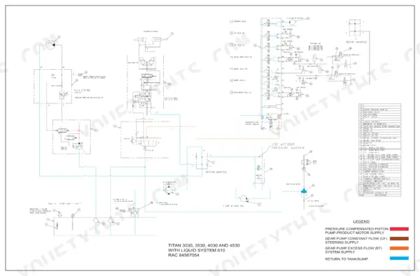
| Towing, Special Tools and Schematics | 1082-1104 | Towing and Parking Brake Release, Special Tool Index, Chassis Electrical Schematic RAC 84567055, Hydraulic Schematics RAC 84567054 with Liquid System 610 and Flex Air 810 |
Quick Reference Specifications
| Specification | Value | Page |
|---|---|---|
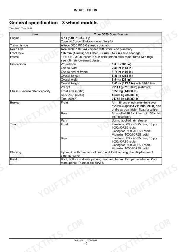
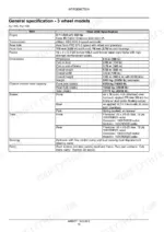
| Engine (Titan 3030, 4030) | 8.7 l (530 in³) 330 Hp, Case IH Cursor, tier 4A | p. 14 |
| Engine (Titan 3530, 4530) | 8.7 l (530 in³) 400 Hp, Case IH Cursor, tier 4A | p. 15 |
| Transmission | Allison 3000 RDS 6 speed automatic | p. 14 |
| Rear axle | Axle Tech PRC 674 2 speed with wheel end planetary | p. 14 |
| Front axle (3 wheel) | 115 mm (4.53 in) solid shaft, 70 mm (2.76 in) axle bearings | p. 14 |
| Front axle (4 wheel) | Axle Tech MS-25, 162 mm (6.375 in) tubular drop axle | p. 16 |
| Chassis rated capacity, total static (3 wheel) | 21772 kg (48000 lb) | p. 14 |
| Chassis rated capacity, total static (4 wheel) | 22680 kg (50000 lb) | p. 16 |
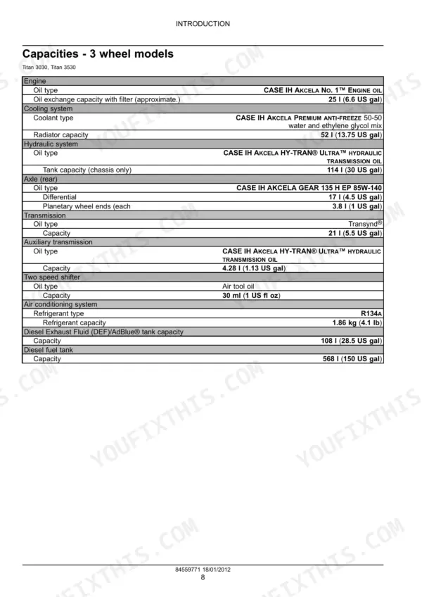
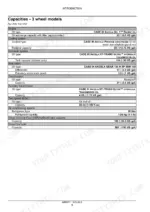
| Engine oil capacity with filter (approximate) | 25 l (6.6 US gal) | p. 12 |
| Radiator capacity | 52 l (13.75 US gal) | p. 12 |
| Hydraulic tank capacity (chassis only) | 114 l (30 US gal) | p. 12 |
| Transmission oil capacity (Transynd®) | 21 l (5.5 US gal) | p. 12 |
| DEF/AdBlue® tank capacity | 108 l (28.5 US gal) | p. 12 |
| Diesel fuel tank capacity | 568 l (150 US gal) | p. 12 |
| Maximum air pressure | 8.3 bar (120 psi) | p. 75 |
| Air system relief valve | 10 bar (150 psi) | p. 77 |
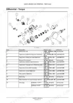
| Rear axle mounting bolt torque | 1220 - 1464 N·m (900 - 1080 lb ft) | p. 905 |
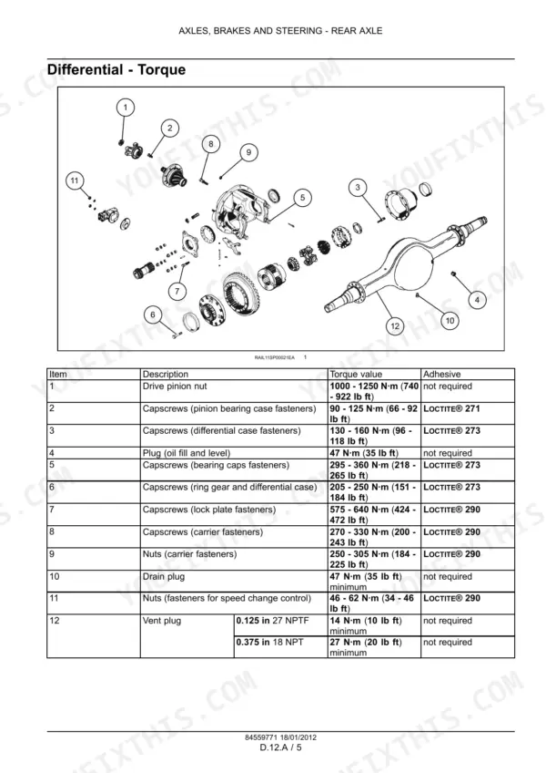
| Drive pinion nut torque | 1000 - 1250 N·m (740 - 922 lb ft) | p. 907 |
| Front toe-in (4 wheel) | 0 - 1.5850 mm (0 - 0.0624 in) | p. 901 |
Case IH Titan 3030, 3530, 4030, 4530 Common Problems This Manual Covers
ATC sets fault code 129, high pressure switch cycling error
The ATC fault code section defines code 129 as a cycling error that happens 2 times in 1 minute. Start by inspecting the harness and connectors. Then check the A/C charge. If it is wrong, recover the R134A, evacuate and recharge the system. Switch continuity should read less than 1.0 Ω. Test for an open circuit to the ATC controller before you replace the controller (page 272).
Manual Section: Fault Codes: Automatic Temperature Control (111-134) p. 272Engine ECU sets code 3006, coolant temperature sensor signal not plausible
Code 3006 means the coolant temperature signal to the ECU is erratic or intermittent, so the ECU substitutes a default value. Possible causes are a bad sensor, faulty wiring or an intermittent connection, the ECU itself, or supply voltages and grounds. Inspect the connector with the key off. Then check for approximately 5 volts (DC) supply with the key on and the engine off (page 361).
Manual Section: Fault Codes: Engine Control Unit (3001-3612) p. 361Front tires wearing fast on a 4 wheel Titan 4030 or 4530
Incorrect toe-in causes rapid tire wear. The spec is 0 - 1.5850 mm (0 - 0.0624 in), measured with a trammel bar as the back distance minus the front distance. Turn the cross tube to adjust, then tighten the tube clamp nut and bolt to 55 - 81 N·m (40 - 60 lb ft), page 901. While you are there, check knuckle vertical end play. The upper king pin bushing is worn if the dial indicator moves a total of 0.254 mm (0.010 in), page 893.
Manual Section: Front Axle p. 901Rear brake shoes worn out and the spring brake has to be caged before the drum comes off
Service brakes are air applied and spring released, and the park brakes are spring applied (page 976). To release brake tension, remove the cage bolt from the air chamber. Insert the cage release bolt with its nut and washer into the top of the chamber, then tighten the nut (page 996). The rest of the chapter covers rear axle brake removal, shoe replacement and installation.
Manual Section: Service Brakes (Pneumatic) p. 996Frequently Asked Questions
The park brake will not release on a dead Titan 3530 floater. How do I tow it?
Park brakes are spring applied and air released, so with no air in the system they stay on (page 976). Run air to the coupler behind the left hand front swing out steps, to approximately 75 psi. Or release them by hand: insert the stored bolt mechanism into each brake chamber behind the rear axle and tighten the nut. If you are towing more than a short distance, remove the drive shaft first. For a stuck unit, rig the chain in a Y shape and pull as straight as possible, because a sideways pull can damage the axles (page 1085). p. 1085
My Titan 4530 has a DEF fault. Where do I start on a urea tank or pressure code?
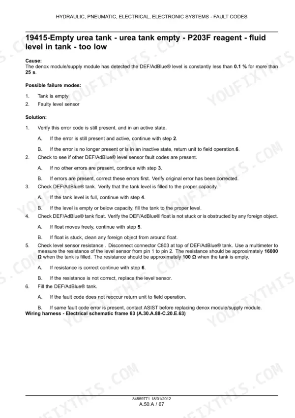
Code 19415 means the supply module saw a DEF/AdBlue level below 0.1 % for more than 25 s. Check the tank level and make sure the float is not stuck. Then measure level sensor resistance: approximately 16000 Ω full and approximately 100 Ω empty (page 319). Contact ASIST before you replace the supply module. Code 19298 means DEF/AdBlue pressure did not reach 500 kPa within 2.5 min at start. Check the feeding tubes, connectors and O-rings for air leaks, then run the UDST with the EST (page 305). p. 319
What are the rear axle and differential torque specs on the Titan 3030, 3530, 4030 and 4530?
Rear axle mounting bolts are 1220 - 1464 N·m (900 - 1080 lb ft), page 905. On the final drive, the wheel bearing nut is 271 N·m (200 lb ft) and the planetary assembly bolts are 115 - 156 N·m (85 - 115 lb ft), page 906. The drive pinion nut is 1000 - 1250 N·m (740 - 922 lb ft), and Loctite is specified on the case and carrier capscrews (page 907). Differential shimming is in the same chapter. p. 905
Can I rebuild the Cursor engine on a Titan 4530 with this manual?
No. The engine chapter covers only torque, special tools, and removal and installation for 3 wheel and 4 wheel models (page 574). It does give the numbers for the swap. M22 engine mount to frame bolts are 800 N·m (590 lb ft), engine to transmission bolts 49 - 58 N·m (36 - 43 lb ft), and torque converter bolts 28 N·m (21 lb ft), page 575. You will need a different source for internal engine work. p. 574
How do I change the hydraulic oil and filter on a Titan 3030, and how much does the tank hold?
The chassis hydraulic tank holds 114 l (30 US gal) of CASE IH AKCELA HY-TRAN ULTRA (page 12). The tank is pressurized, so vent it first by slowly loosening the breather. Drain it, then replace the return filter element under the top cover, which has four bolts. Refill through the plug in the top of the in-tank return filter and check the level gauge. Run the engine at 1500 RPM in neutral with the park brake on for at least 20 minutes. Recheck the level, then run at least 1 hour under load (page 52). p. 52




Reviews
There are no reviews yet.