Part of the Case IH Repair Manuals.
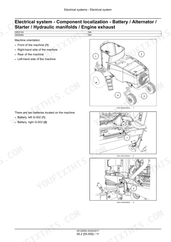
This is the Case IH service manual for the WD2104 and WD2504 Tier 4B (final) self-propelled windrowers, PIN YGG677501 and above, North America. It is part number 48126554, 1st edition April 2017.
It covers both draper ready and non-draper ready machines. That includes the NEF engine's fuel, cooling, SCR and lubrication service, plus the hydrostatic drive and splitter gearbox. It also covers the header drive pumps, the lift and charge circuits, A/C, the schematic sheets and the fault code cards.
What's Inside This Case IH WD2104, WD2504 Manual
| System | Pages | Key Topics |
|---|---|---|
| Introduction | 1-65 | Cover, Product and Engine Link, Contents, Safety Rules, Minimum Tightening Torques, General Specification, Capacities and Lubrication, Ground Speed Chart, Ballast Requirements |
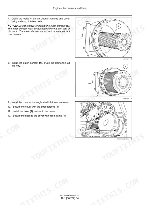
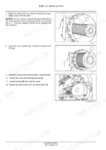
| Engine Air Cleaners and Lines | 66-71 | Primary and Secondary Air Filter Replacement |
| Engine Fuel Injection System | 72-88 | Fuel Injection System Test, Low Pressure Pump Testing, Pressure Relief Valve, High Pressure Flow Regulator, Fuel Injectors, Injector Code |
| Engine Cooling System | 89-103 | Coolant Check and Replacement, Fan and Accessory Belt Replacement |
| Engine SCR Exhaust Treatment | 104-113 | SCR Dynamic Description, Configuration, Service, DEF Tank Cleaning and Check |
| Engine Lubrication System | 114-124 | Engine Oil and Filter Replacement |
| Front Axle Final Drives | 125-164 | Planetary Hubs, Special Tools, Remove, Disassemble, Assemble, Install, Change Fluid |
| Non-Powered Rear Axle | 165-204 | Suspended Axle Tubes, Air System, Axle Extension, Wheel Support, Air Spring |
| Hydrostatic Drive | 205-380 | Linkage Alignment, Ground Drive Motors, Relief Valves, Ground Drive Pressure Test, Neutralizer Plate, Splitter Gearbox, Pump and Motor Components |
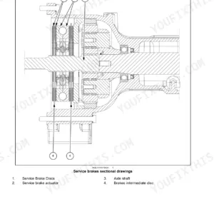
| Parking Brake | 381-399 | Dynamic Description, Exploded View, Remove, Install, Bleed Brake Control Valve |
| Hydraulic Systems Overview and Schematics | 400-518 | Capacity, Hydraulic Symbols, Reservoir, Pumps and Manifolds, Header Flotation, Draper and Non-Draper Hydraulic Schematic Frames, Troubleshooting |
| Main Lift System and Charge Pump | 519-671 | Float Manifold Solenoids, Header Lift Relief Pressure Test, Lift Cylinders, Charge Pump Relief Valve Test, Reservoir, Cooler and Filters, Header Height, Tilt and Leveling |
| Header Hydraulic Drive | 672-759 | Disc and Draper Header Drive Pumps, Start-Up Procedure, Pressure Test, Pump Neutral Adjustment, Pump Overhaul, Header Drive Motor Troubleshooting |
| Frames and Ballasting | 760-776 | Lift Arm Position Sensor, Ballast Weight Requirements |
| Steering | 777-817 | Steering Column, Gas Struts, Steering Wheel, Hydraulic Control Components, Autoguidance Steering |
| Wheels | 818-829 | Front Wheels and Ground Speeds |
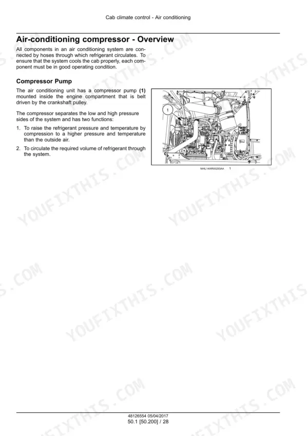
| Cab Climate Control | 830-917 | Air Conditioning Specifications, Dynamic Description, Service, Recover, Evacuate and Charge, Component Replacement, Troubleshooting |
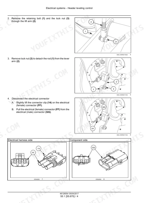
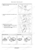
| Electrical Header Leveling Control | 918-926 | Header Positioning Sensor Removal (P918) and Installation (P921), Header Leveling Control Index, Electrical System Section Contents |
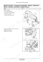
| Electrical System Calibrations and Tests | 927-1202 | Universal Control Module Pin Tables, Battery and Alternator, Starting System, Calibrations, Charging Circuit Inspection, Electrical Tests, Sensor and Solenoid Replacement |
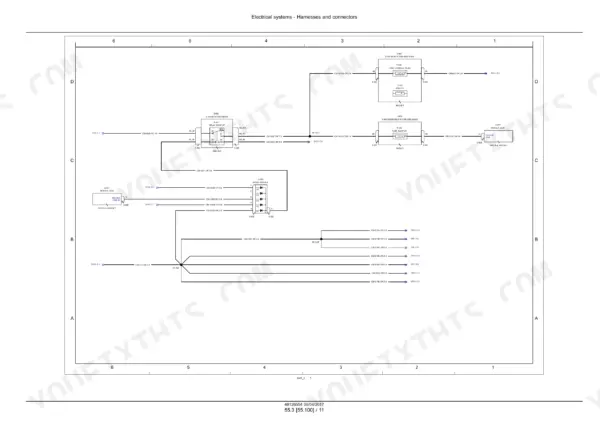
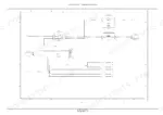
| Electrical Harnesses and Schematics | 1203-2103 | Electrical Schematic Sheets for Non-Draper and Draper Machines, Component and Connector Diagrams, Engine Schematics |
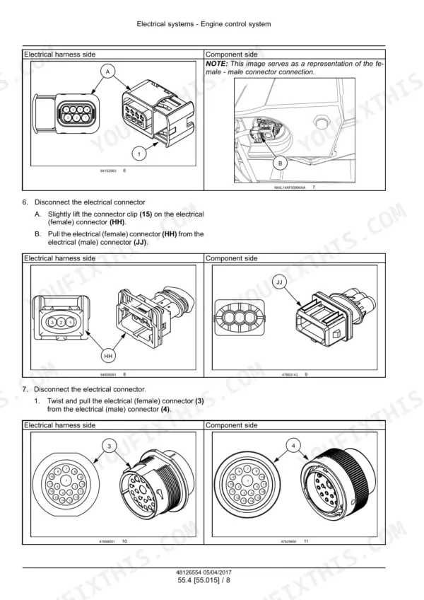
| Electrical Control Systems | 2104-2619 | Engine Control, Starting, Alternator, Battery, SCR Electrical System, Hydrostatic Drive Control, Cab Controls, HVAC Control, Header Controls, Lighting, Autoguidance |
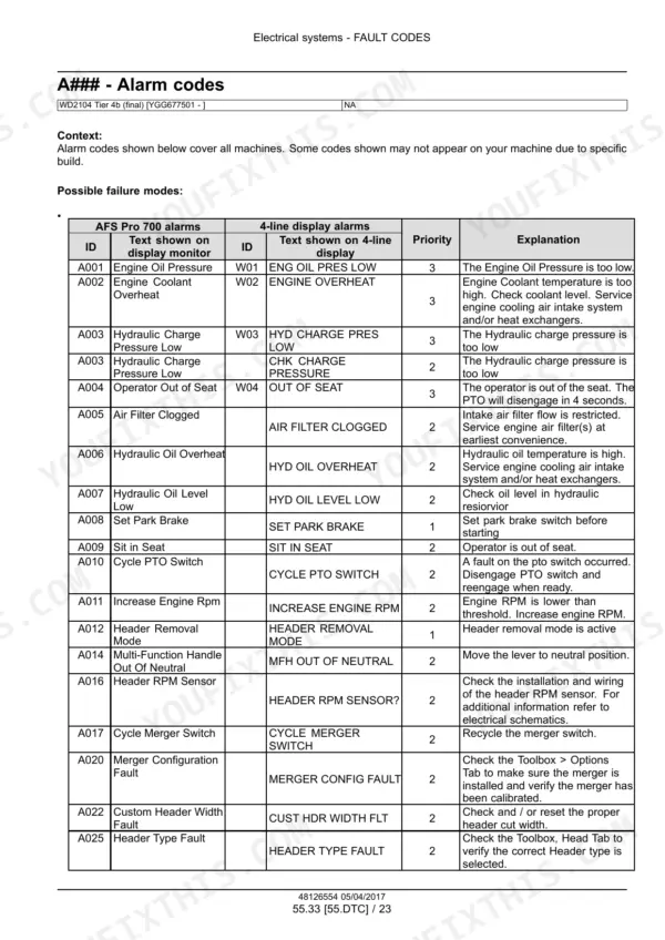
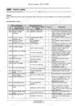
| Electrical Fault Codes | 2620-3977 | Alarm and Abort Codes, ATC Codes, ECU DTC Cards, UCM Error Cards and SCR Codes with Possible Failure Modes and Solution |
| Platform, Cab and Bodywork | 3978-4051 | Operator Seat, Cab, Cab Interior, Cab Doors and Hatches |
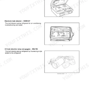
| Special Tool Index | 4052-4069 | Special Tool Index with Genuine Reference Numbers (Fuel and Hydraulic Pressure Gauges, Portable a/C Recovery and Recharge Unit), Back Cover, Closing Fold-Out Schematic Sheets |
Quick Reference Specifications
| Specification | Value | Page |
|---|---|---|
| Engine displacement, NEF 6-cylinder | 6.7 L (409 in³) | p. 49 |
| Engine power, WD2104 / WD2504 | 157 kW (210 Hp) / 187 kW (250 Hp) | p. 49 |
| Engine peak torque at 1600 RPM, WD2104 / WD2504 | 915 N·m (675 lb ft) / 1065 N·m (786 lb ft) | p. 49 |
| Engine rated speed | 2200 RPM | p. 49 |
| Engine crankcase oil with filter | 16 l (16.9 US qt) | p. 49 |
| Cooling system capacity | 25.7 L (27.2 US qt) | p. 49 |
| Fuel tanks, two tanks total | 454 L (120 US gal) | p. 49 |
| Diesel Exhaust Fluid (DEF) tank | 72 L (19 US gal) | p. 49 |
| Hydraulic system reservoir | 41.6 l (11 US gal) | p. 49 |
| Total hydraulic system, draper units | 68.1 l (18 US gal) | p. 49 |
| Planetary final drive oil, each | 0.89 l (0.94 US qt) | p. 49 |
| Alternator output | 150 A | p. 49 |
| Drive wheel lug nut torque | 400 N·m (295 lb ft) | p. 151 |
| DEF supply system stabilized pressure | 9.0 bar (130.5 psi) | p. 104 |
| Steering circuit relief valve | 138 bar (2000 psi) | p. 439 |
| Header lift relief pressure test | 217.8 - 222.2 bar (3158.1 - 3221.9 psi) | p. 557 |
| Charge pressure relief valve test, neutral | 20.7 - 22.8 bar (300 - 330 psi) | p. 573 |
| Draper header drive pump case pressure, cold maximum | 5.2 bar (75 psi) | p. 722 |
| Draper header drive pump neutral pressure check | 21 - 23 bar (300 - 330 psi) | p. 727 |
| A/C refrigerant R134A capacity | 2.2 kg (4.85 lb) | p. 830 |