
Part of the Hyundai Repair Manuals.
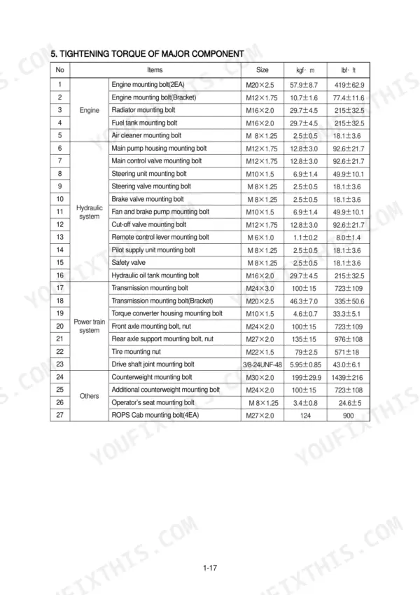
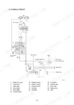
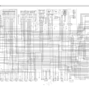
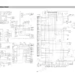
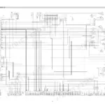
All 401 pages of this Hyundai HL757TM-7 service manual PDF focus on one machine: the HL757TM-7 Wheel Loader, from the power train out to the boom and bucket. You get complete electrical circuit diagrams with connector pinouts and monitoring system coverage, plus hydraulic schematics tracing the brake, steering, and work equipment circuits. Every system gets the full treatment: operational checks, troubleshooting charts, tests and adjustments, and step-by-step disassembly and assembly. The main pump pushes 51+51 cc/rev at a maximum of 210 kgf/cm2 (2990 psi); torque the pump housing mounting bolts to 12.8 plus or minus 3.0 kgf-m before you button it back up. Your loader is down, and forum threads won't fix it. This PDF is bookmarked with a real text layer; type in a spec, jump straight to the page, and get back to work.
What's Inside This Hyundai HL757TM-7 Manual
| System | Pages | Key Topics |
|---|---|---|
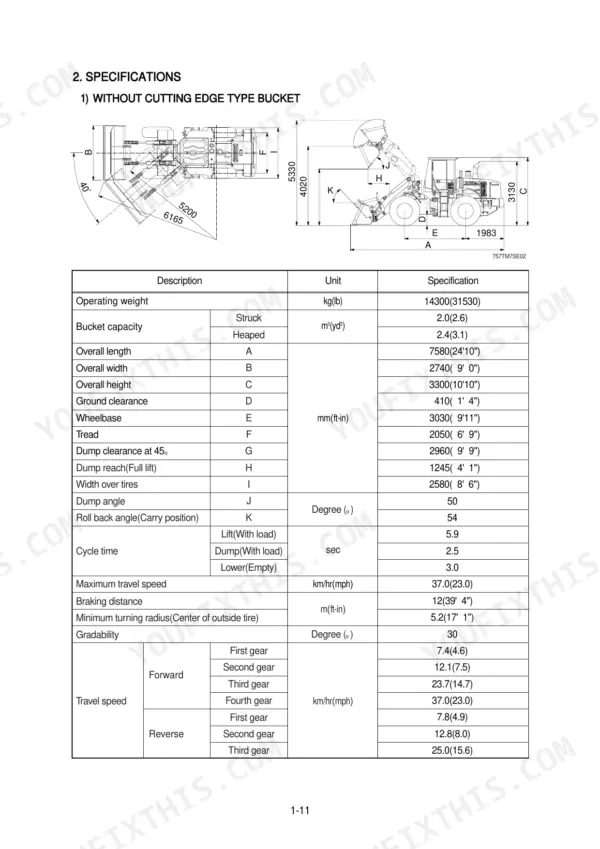
| General | 1-34 | Safety Hints, Specifications, Operational Checkout Record Sheet |
| Engine | 35-39 | Structure, System Diagrams |
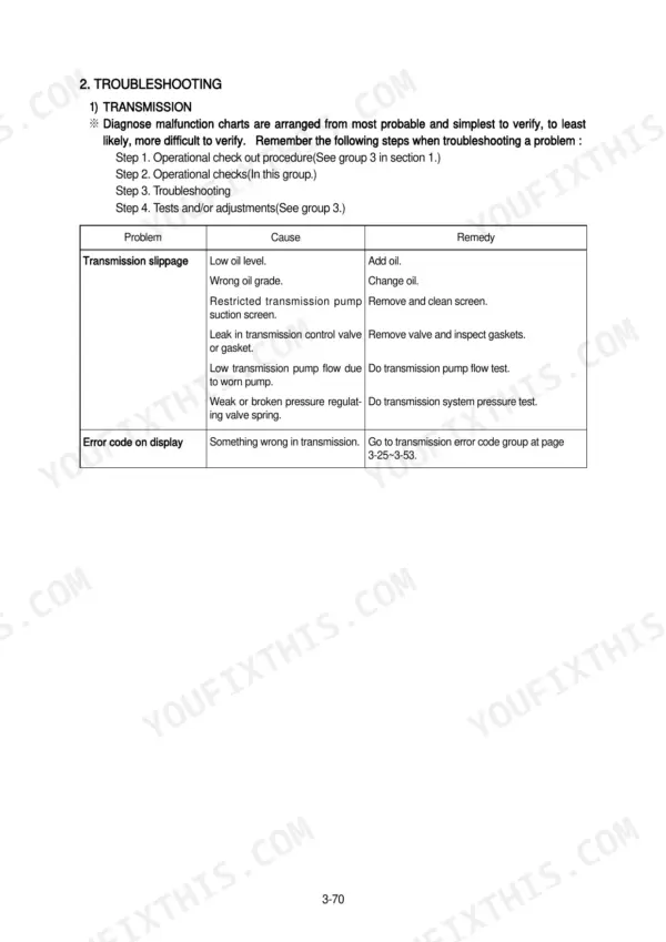
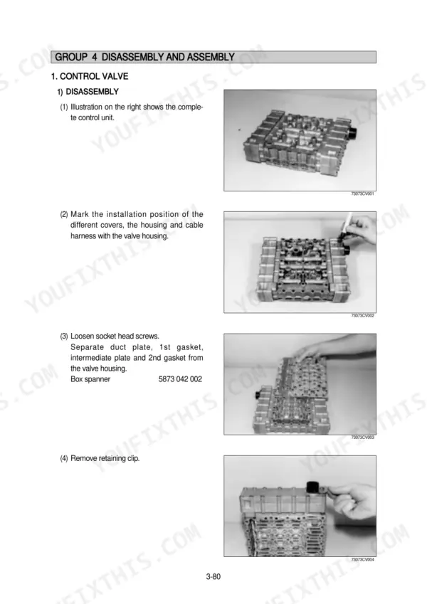
| Power Train System | 40-143 | Structure and Function, Operational Checks and Troubleshooting, Test and Adjustments, Disassembly and Assembly |
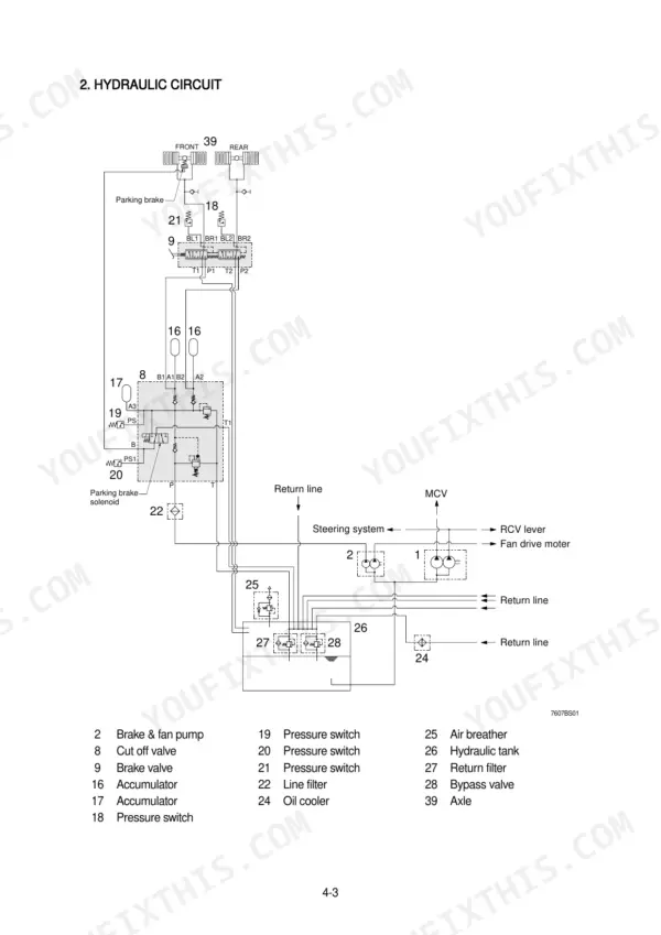
| Brake System | 144-183 | Structure and Function, Operational Checks and Troubleshooting, Tests and Adjustments, Disassembly and Assembly |
| Steering System | 184-244 | Structure and Function, Operational Checks and Troubleshooting, Tests and Adjustments, Disassembly and Assembly |
| Work Equipment | 245-325 | Structure and Function, Operational Checks and Troubleshooting, Tests and Adjustments, Disassembly and Assembly |
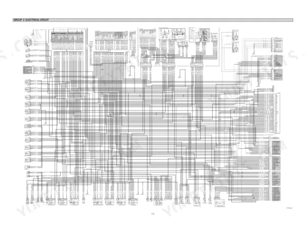
| Electrical System | 326-401 | Component Location, Electrical Circuit, Monitoring System, Electrical Component Specification, Connectors, Troubleshooting |
Quick Reference Specifications
| Specification | Value | Page |
|---|---|---|
| Main pump housing mounting bolt torque | 12.8 ± 3.0 kgf·m | p. 28 |
| Main control valve mounting bolt torque | 12.8 ± 3.0 kgf·m | p. 28 |
| Main pump capacity | 51+51cc/rev | p. 26 |
| Main pump maximum operating pressure | 210kgf/cm² (2990psi) | p. 26 |
| Boom cylinder bore dia × rod dia × stroke | Ø140 × Ø75 × 750mm | p. 27 |
| Bucket cylinder bore dia × rod dia × stroke | Ø120 × Ø65 × 755mm | p. 27 |
| Maximum pressure on the EF port | 210 bar | p. 191 |
| Steering valve relief pressure | 20.1~21.1MPa (205~215bar, 2900~3100psi) | p. 212 |
| Bypass valve set pressure | 1.36kg/cm2 (19.3psi) | p. 277 |
| Maximum pressure at steering valve (EHPS) | 2 MPa (20 bar, 285 psi) | p. 298 |
| Maximum pressure at main control valve | 1 MPa (10 bar, 145 psi) | p. 298 |
| Hydraulic oil filter replacement interval | 250 operating hours | p. 305 |
Hyundai HL757TM-7 Common Problems This Manual Covers
Hyundai HL757TM-7 hydraulic pump whines under load, boom lifts slow, bucket feels weak
Check hydraulic oil level first, then pull the suction strainer and look for a plugged screen. Replace the hydraulic filter element if it has more than 250 hours on it, the interval spec on page 305. Bleed air from the suction line and test main relief pressure against the 210 kgf/cm² spec on page 26.
Manual Section: Work Equipment Troubleshooting p. 245Boom drifts down with a loaded bucket parked, cylinders vibrate during slow lift
Test for internal leakage before condemning the pump: dead-head the boom and watch for rod creep. Rebuild leaking cylinders with new piston seals and packing, then torque the gland to 70 ± 7 kgf·m and the piston to 50 ± 5 kgf·m using the table on page 232. Bleed all air after reassembly.
Manual Section: Work Equipment Troubleshooting p. 232Steering feels heavy at idle, oil temperature climbs, wheel kicks back over rough ground
Verify steering relief pressure first; the valve should crack between 20.1 and 21.1 MPa (205 to 215 bar) per the spec on page 212. If pressure checks good, pull the priority valve and inspect the spool and orifice plugs for a restriction. Missing or wrong orifice plugs will overheat the steering circuit fast.
Manual Section: Steering System Troubleshooting p. 184Transmission won't shift, dash gear display stays frozen when moving the column selector
Check supply voltage at the TCU connector; you need 20 to 30 V with the key on, per the spec on page 396. Measure harness resistance from the column selector to the controller: anything over 1 ohm means a bad connection. Clean and reseat connectors before replacing the TCU, then work the transmission troubleshooting steps starting.
Manual Section: Transmission TroubleshootingBrake pedal goes soft after engine shutdown, warning buzzer sounds at low accumulator pressure
Test the brake charge circuit pressure first: the pump should deliver up to 150 kgf/cm² per the spec on page 152. Soap-test every hose, fitting, and valve for leaks with the system charged. Replace hardened compressor gaskets and any weeping fittings, then confirm the accumulators hold pressure overnight before releasing the machine.
Manual Section: Service Brake Troubleshooting p. 144Frequently Asked Questions
What do Hyundai HL757TM-7 error codes 010, 011, 012, 013, 014, and 015 mean?
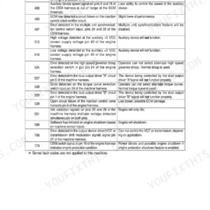
These error codes relate to the electrical system. Code 010 indicates power input voltage low (below 18V), 011 indicates power input voltage high (above 38V), 012 indicates alternator voltage low (below 5V), 013 indicates alternator voltage high (above 36V), 014 indicates a buzzer circuit open or short to ground, and 015 indicates a buzzer circuit short to power. p. 357
How do I check steering pressure on a Hyundai HL757TM-7?
To check the steering valve relief pressure, connect a 0-35MPa (0-5000psi) gauge to the test port. Run the engine at high idle and turn the steering wheel rapidly while holding approximately 22N (5lb force) on the wheel with the frames locked. The pressure should be 20.1-21.1MPa (2900-3100psi). p. 212
What are the replacement specifications for the hydraulic oil filter element?
The hydraulic oil filter element in the hydraulic oil tank should be replaced every 250 operating hours or more often if debris is found during inspection. p. 305
What is the tightening torque for the main pump stud and flanged nut?
The tightening torque for the main pump flanged nut (18) is 23.2 kgf·m (168 lbf·ft). p. 312
What is the standard clearance for the bucket rollback circuit relief valve?
The standard clearance for the bucket rollback circuit relief valve is not specified, but the relief pressure for the bucket rollback (R) is 240±5 kg/cm² (3414±70 psi). p. 296
Is this Hyundai HL757TM-7 Service Manual a digital download?
One searchable PDF covering 401 pages, delivered instantly. No disc, no shipping, no waiting on the post.
Am I free to print this Hyundai HL757TM-7 Service Manual?
Yes. Print individual pages or full chapters for your own shop use, on letter or A4 paper.








Reviews
There are no reviews yet.