
Part of the Hyundai Repair Manuals.
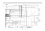
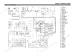
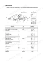
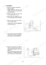
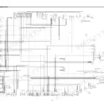
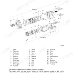
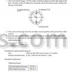
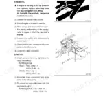
All 626 pages of this Hyundai R200W-3 Service Manual PDF cover one machine: the R200W-3 wheeled hydraulic excavator, from pump device to final drive. You get full hydraulic schematics with main and pilot circuit routing, electrical wiring diagrams with component locations, and a troubleshooting section that walks the hydraulic and mechanical systems fault by fault. Inside: step-by-step disassembly and assembly procedures for the main pump, control valve, swing device, steering valve, every cylinder, and both axles, plus tightening torque tables for metric bolts, pipes, and hoses. Set the main relief valve at 320 kgf/cm2 normal, 350 on power boost, and check solenoid resistance at 15-25 Ohm before you blame the harness. No more chasing wiring faults with a multimeter and a prayer. Bookmarked and text-searchable; jump straight to the spec and get back under the machine.
What's Inside This Hyundai R200W-3 Manual
| System | Pages | Key Topics |
|---|---|---|
| General | 1-26 | Safety, Specification |
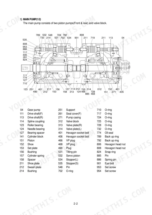
| Structure and Function | 27-114 | Pump Device, Main Control Valve, Swing Device, Travel Motor |
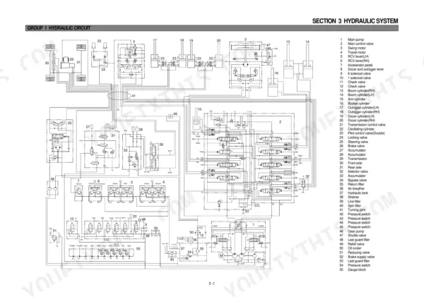
| Hydraulic System | 115-147 | Hydraulic Circuit, Main Circuit, Pilot Circuit |
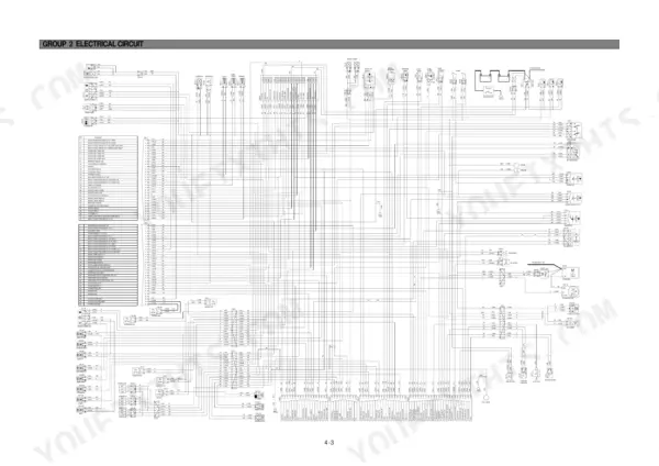
| Electrical System | 148-197 | Component Location, Electrical Circuit |
| Mechatronics System | 198-239 | Outline, Mode Selection System |
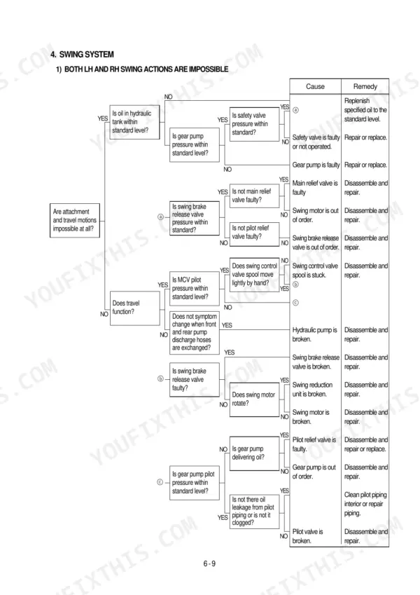
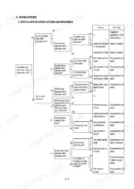
| Troubleshooting | 240-295 | Before Troubleshooting, Hydraulic and Mechanical System |
| Maintenance Standard | 296-321 | Operational Performance Test, Track and Work Equipment |
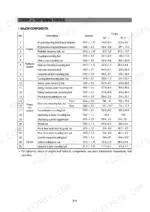
| General Precautions and Tightening Torques | 322-342 | Removal Work, Installation Work, Tightening Torque, Metric Bolt Torque, Pipe and Hose Torque |
| Main Pump Disassembly and Assembly | 343-350 | Regulator Disassembly, Main Pump Disassembly, Main Pump Assembly, Tools, Tightening Torque |
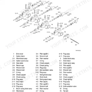
| Main Control Valve Disassembly and Assembly | 351-368 | Main Relief Valve, Port Relief Valve, Arm Spool, Boom Spool, Travel Spool |
| Swing Device Disassembly and Assembly | 369-386 | Swing Motor Removal, Swing Motor Disassembly, Swing Motor Assembly, Reduction Gear Removal, Reduction Gear Disassembly |
| Steering Valve Disassembly and Assembly | 387-418 | Steering Valve Structure, Steering Valve Disassembly, Steering Valve Assembly, Tools, Tightening Torque |
| Cylinder Disassembly and Assembly | 419-518 | Rcv Lever, Bucket Cylinder, Arm Cylinder, Boom Cylinder, Dozer Cylinder, Outrigger Cylinder |
| Axle and Final Drive Disassembly and Assembly | 519-618 | Front Axle Removal, Rear Axle Removal, Differential Disassembly, Final Drive Disassembly, Brake Lining Wearing Test |
| Foreword and Conversion Tables | 619-626 | Service Manual Structure, Conversion Tables, Temperature Conversion |
Quick Reference Specifications
| Specification | Value | Page |
|---|---|---|
| Main relief valve setting pressure (normal) | 320 kgf/cm2 | p. 122 |
| Main relief valve setting pressure (power boost) | 350 kgf/cm2 | p. 122 |
| Solenoid valve resistance | 15-25 Ohm | p. 172 |
| EPPR valve resistance | 15-25 Ohm | p. 172 |
| Port relief valve (602) plug (102) torque | 7.0 ~ 8.0 kgf·m (50.6 ~ 57.8 lbf·ft) | p. 358 |
| Socket head bolt (Bucket cylinder, M18) | 32 ± 3.0 kgf·m (231.5 ± 21.7 lbf·ft) | p. 607 |
| Socket head bolt (Boom cylinder, M20) | 46 ± 5.0 kgf·m (332.7 ± 36.2 lbf·ft) | p. 607 |
| Engine Oil Quantity | 24 L | p. 22 |
| Main Pump Rated Pressure | 320 kg/cm2 | p. 22 |
| Swing Motor Relief Pressure | 240 kg/cm2 | p. 23 |
| Travel Motor Relief Pressure | 350 kg/cm2 | p. 23 |
| Swing Parking Brake Releasing Pressure | 40 kgf/cm2 | p. 310 |
Hyundai R200W-3 Common Problems This Manual Covers
Hyundai R200W-3 all hydraulic functions weak, boom bucket and travel losing pressure under load
Tee a pressure gauge into the pump outlet port and stall the bucket circuit at full rpm. Compare readings against the main relief setting of 320 kgf/cm2 normal and 350 kgf/cm2 on power boost listed on page 122. If one pump side reads low, adjust or replace that relief cartridge before condemning the pump.
Manual Section: Hydraulic System p. 122Bucket or boom cylinder drifts down in neutral, one work function weak while others operate normally
Swap the suspect port relief valve with the matching valve from a circuit that works, then retest. If the fault follows the valve, replace it; the opening pressure has drifted low. Clean the seat before installing and torque the plug to 7.0 to 8.0 kgf·m (50.6 to 57.8 lbf·ft) per the chart on page 358.
Manual Section: Main Control Valve Disassembly and Assembly p. 358Boom will not lower when commanded, lifting very slow with loud hydraulic noise
Remove the boom hold valve from the control valve housing and inspect for dirt jamming the check element or a plugged orifice. Clean parts in fresh solvent, never with wire that could scar the bore. Follow the disassembly sequence starting on page 351, and torque the main relief valve assembly to the value in the control-valve tightening-torque chart if it was disturbed.
Manual Section: Main Control Valve Disassembly and Assembly p. 351Joystick controls unresponsive or laggy, suspect no pilot pressure reaching the main control valve
Check pilot pressure at the remote control valve before pulling anything apart. Then test the safety solenoid electrically: disconnect the connector and measure resistance across terminals 1 and 2, looking for 15 to 25 Ohm as shown on page 172. An open or shorted coil means no pilot oil, so replace the solenoid.
Manual Section: Electrical System p. 172Hydraulic response gets sluggish once oil warms up, all functions slow after an hour of digging
Drain a fluid sample and check for cloudiness, which points to water or aeration. Verify tank level and replace clogged return filters. Then run the operational performance test: compare main pump delivery pressure at high idle against the standard given in the operational performance test on page 311. Low readings with hot oil mean internal pump leakage.
Manual Section: Maintenance Standard p. 311Frequently Asked Questions
How do I delete all recorded error codes on the Hyundai R200W-3?
To delete all recorded error codes, select the recorded error (TIME Err) display on the cluster. Then, press the engine speed up and down switches at the same time for 2 seconds or more. The cluster display will change to 'TIME Err : 00', indicating that the CPU controller has deleted all recorded errors from the memory. p. 216
What do the error codes mean on a Hyundai R200W-3?
Error codes indicate specific malfunctions in the machine's electrical or mechatronics systems, such as short circuits or open circuits in sensors and valves. For example, 'Err : 01' indicates a short circuit in the governor motor lines, while 'Err : 12' indicates the P1 pressure sensor is shorted to battery(+). A complete list of these codes and their corresponding problems can be found in the Error Codes Table on page 217. p. 217
What is the tightening torque for the main pump mounting bolts on the R200W-3?
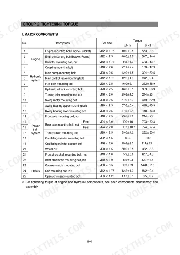
The tightening torque for the main pump mounting bolts (M20 x 2.5) is 42.0 ± 4.5 kgf·m (304 ± 32.5 lbf·ft). p. 325
How do I bleed the air from the hydraulic pump after installation?
To bleed the air from the hydraulic pump, first remove the air vent plug (2EA). Tighten the plug lightly, then start the engine and run it at low idling until oil comes out from the plug. Finally, tighten the plug fully. p. 329
What is the standard clearance for the brake lining piston stroke?
The permitted piston stroke for the brake lining is a maximum of 6.25mm. In new condition, the plate pack piston stroke should be between 2.4mm and 2.8mm. p. 522
Do I get instant access to this Hyundai R200W-3 Service Manual?
Instant PDF download. You get the full 626-page searchable Service Manual immediately after payment. Open it on your laptop, tablet, or phone right in the shop.
Am I able to print pages from this Hyundai R200W-3 manual?
Yes. It prints from any PDF reader, so run off the pages you need for your own repair work.







Reviews
There are no reviews yet.