


Part of the JCB Repair Manuals.
Need the factory specs for your JCB Mini Backhoe Loader? This 377-page JCB Mini CX, KD 103-10, 403C-11 Service Manual PDF (OEM #9803/9340-8) breaks down every transmission teardown, steering rebuild, and electrical procedure. Open to the hydraulics section to find complete schematics covering both 2WD and 4WD drive motor circuits, plus step-by-step problem-solving charts for the hydrostatic transmission. You get clear wiring diagrams, complete loader arm removal instructions, and factory torque settings. Dial in the Main Relief Valve (MRV) setting exactly to 200 bar and secure the front and rear wheel nuts to the correct torque before rolling it out of the bay. Your shop space is tied up and every hour costs money. Download this bookmarked file, jump straight to the spec you need, and fix the machine right the first time.
What's Inside This Manual
| System | Pages | Key Topics |
|---|---|---|
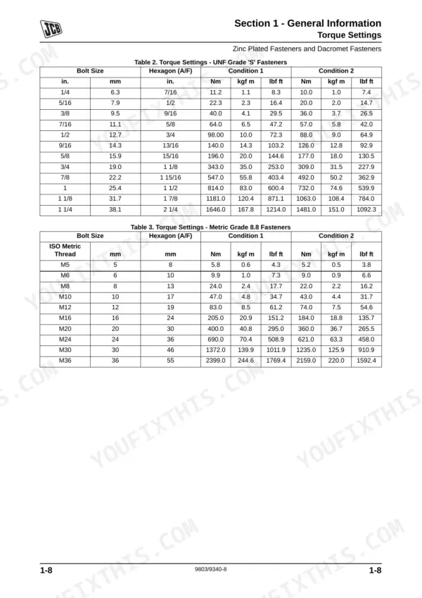
| General Information | 2-35 | Introduction, Torque Settings, Service Tools, Consumables |
| Care & Safety | 36-55 | Safety Notices (Important Information, Safety Checklist, Safety Decals), Important Information (Operator Manual, Safety Warnings), Safety Checklist (Safety - Yours and Others) |
| Attachments | 108-117 | Hoses and Couplings (Quick Release Couplings, Connecting/Disconnecting Hydraulic Hoses), Shovels (Maintenance) |
| Body & Framework | 118-133 | Floor Plates (Removal and Replacement), Loader Arm (Removal and Replacement), Dipper (Removal and Replacement), Boom (Removal and Replacement) |
| Electrics | 134-165 | Technical Data, Test Methods (Using a Multimeter), Service Procedures (Battery), Harness Data (Wire and Harness Number Identification, Harness Drawings) |
| Technical Data | 168 | General Data, Hydraulic Contamination, Cleaning Operation, Introduction to Hydraulic Schematic Symbols |
| Service Procedures | 168 | Hydraulic System Start-Up, Pump Removal and Replacement, Motor Removal and Replacement, Charge Pressure Testing |
| Operation Description | 168 | Hydrostatic Transmission Operation, Drive Circuit Description, Control System Operation |
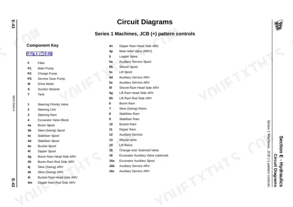
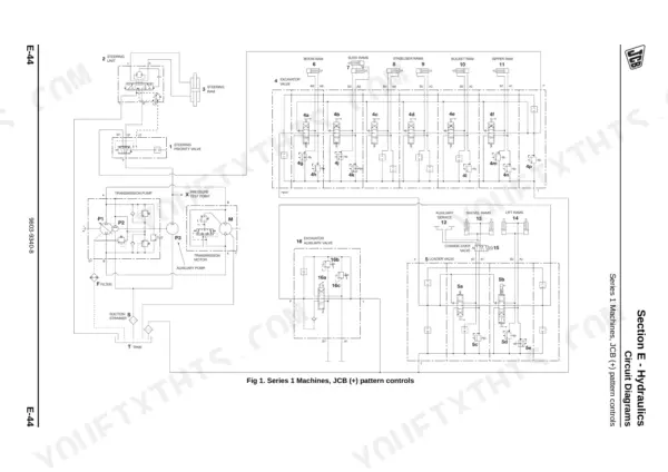
| Circuit Diagrams | 168 | Hydraulic Circuit Diagrams (2WD and 4WD Drive Motor Circuits, Control Valve Circuits) |
| Towing/Winching | 168 | Towing Procedure, Tow Valve Operation, Emergency Drive Bypass |
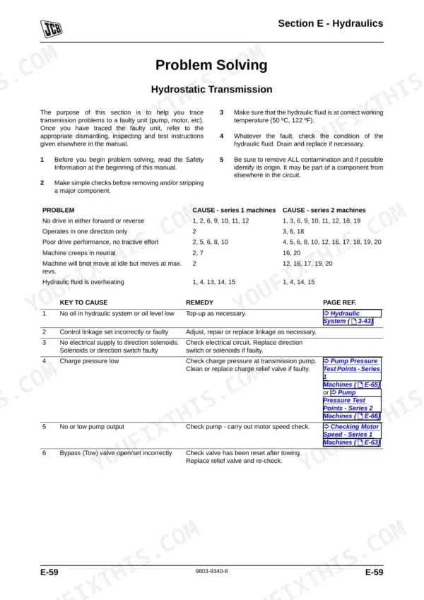
| Problem Solving | 168 | Hydrostatic Transmission Problem Solving Charts, Drive System Fault Diagnosis |
| Pumps | 168 | Transmission Pump (Removal and Replacement, Dismantling and Assembly), Pump Neutral Adjustment |
| Drive Motors | 168 | Drive Motor (Removal and Replacement, Dismantling and Assembly), 2WD and 4WD Motor Circuits |
| Valves | 168 | Main Relief Valve (Mrv), Auxiliary Relief Valves (Arv), Control Valve Service |
| Rams | 168 | Hydraulic Ram (Removal and Replacement, Dismantling and Assembly, Seals) |
| Oil Cooler | 169 | Oil Cooler Connections, Removal and Replacement |
| Service Tools | 169-333 | Numerical List of Service Tools, Tool Detail Reference (Section E- Hydraulics), Hydraulic Test Equipment |
| Transmission | 334-349 | Wheels (Wheel Removal and Replacement), Front Axle (Removal and Replacement), Service Tools (Numerical List, Tool Detail Reference Section) |
| Brakes | 350-357 | Parking Brake (Removal and Replacement, Dismantling and Assembly, Testing the Parking Brake) |
| Steering | 358-371 | Hydraulic Steering Unit (Description, Removal and Replacement, Dismantling and Assembly), Power Track Rod (Removal and Replacement |
| Engine | 372-377 | Technical Data (Up to Machine No 1042315, From Machine No 1042316), Technical Data Up to Machine No 1042315 (Speeds, Fuel System, Cooling System) |
Quick Reference Specifications
| Specification | Value | Page |
|---|---|---|
| All Models | ||
| Main Relief Valve (MRV) setting | 200 bar (2900 lbf/in2) | p. 172 |
| Auxiliary Relief Valves (ARV) setting | 215 bar (3117 lbf/in2) | p. 172 |
| Battery Cold Crank Amps | 420 to 585 according to battery type | p. 138 |
| Battery Reserve Capacity | 170 to 230 minutes for 25 Amp load | p. 138 |
| Alternator Output | 12V, 40 Amp | p. 138 |
| Alternator Belt Deflection | 5 mm (0.2 in) | p. 97 |
| BSP Hose Torque (1/8 in) | 14.0 - 16.00 Nm (1.4 - 1.6 kgf m, 10.3 - 11.8 lbf ft) | p. 17 |
| BSP Hose Torque (1/4 in) | 24.0 - 27.0 Nm (2.4 - 2.7 kgf m, 17.7 - 19.9 lbf ft) | p. 17 |
| Air Cleaner Element Replacement Interval | every 100 hours (if working in dusty conditions) | p. 68 |
| 2-wheel drive machines | ||
| Wheel Nut Torque (2WD) | 96 Nm (9.8 kgf m, 71 lbf ft) | p. 106 |
| 4-wheel drive machines | ||
| Wheel Nut Torque (4WD) | 200 Nm (20.4 kgf m, 147 lbf ft) | p. 106 |
| Mini CX, Mini CX 4x4 (all areas except North America) | ||
| Engine Oil Capacity (up to m/c 1042315) | 3.5 Litres | p. 70 |
| Mini CX, Mini CX 4x4 (North America) | ||
| Engine Oil Capacity (from m/c 1042316) | 1.0 US Gal | p. 70 |