Part of the John Deere Repair Manuals.
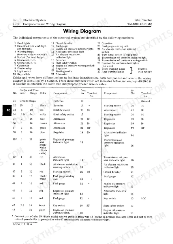
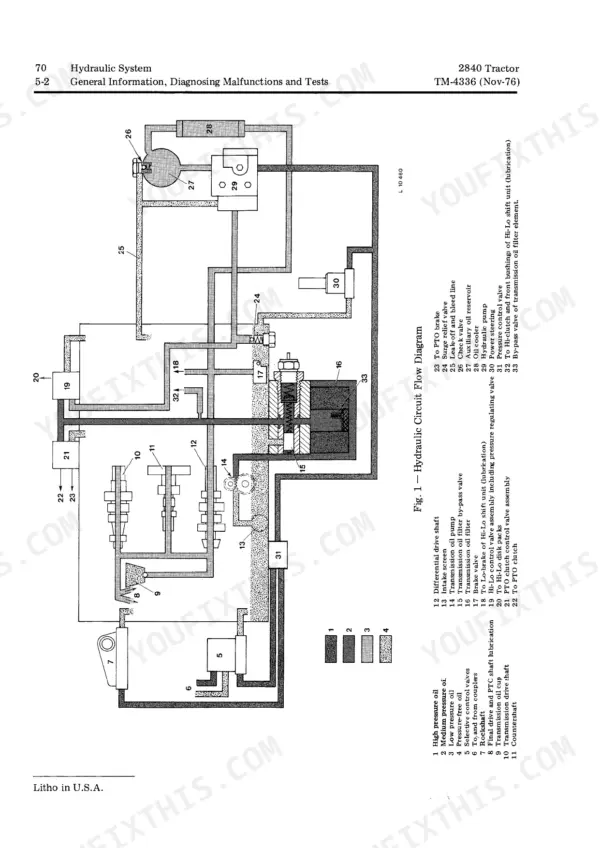
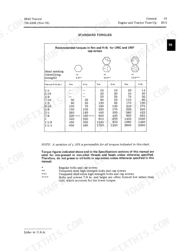
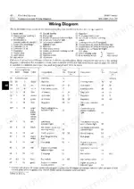
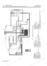
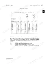
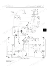
Hydraulic system work is the hardest chapter in TM4336, the 298-page John Deere 2840 technical manual PDF, running from pump and rockshaft to the selective control valve and remote cylinder, then widening to the engine, fuel injection, power train and front axle. Wiring diagrams map the electrical components and charging circuit, while hydraulic schematics trace oil from reservoir and filter through the valves. Power train chapters cover the engine clutch, Hi-Lo shift unit, collar-shift transmission, differential, final drives and PTO clutch. The figures you get are factory. Check pump delivery against 39.5 cm³ (2.40 cu. in.) per shaft revolution, and gauge pressure and return valves to 12.60 to 12.62 mm O.D. When your 2840 is due its after-sales inspection or an engine and tractor tune-up, the General section sets out both checks. Bookmarked and text-searchable, the PDF is yours to keep once bought, ready for each rockshaft or PTO clutch job this tractor brings.
What's Inside This John Deere 2840 Manual
| System | Pages | Key Topics |
|---|---|---|
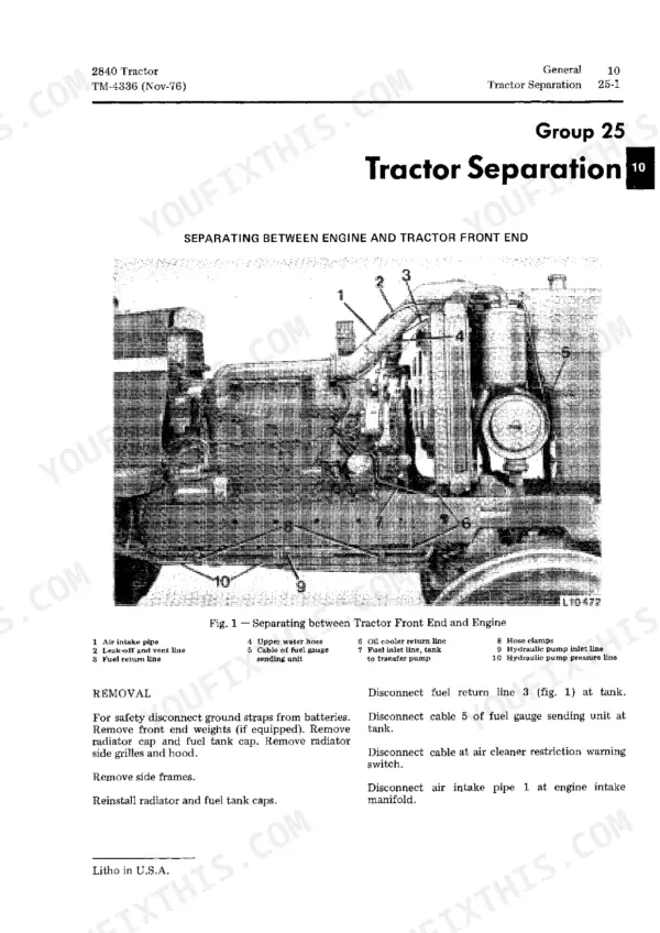
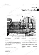
| General | 3-32 | Specifications, Predelivery, Delivery, And After-Sales Inspections, Lubrication, Engine and Tractor Tune-Up, Tractor Separation |
| Engine | 33-90 | General Information, Diagnosing Malfunctions, Cylinder Head and Camshaft, Cylinder Block, Liners, Pistons and Connecting Rods, Crankshaft, Main Bearings and Flywheel |
| Fuel System | 91-110 | Diagnosing Malfunctions, Fuel Tank, Transfer Pump, And Fuel Filter, Roto Diesel Fuel Injection Pump, Fuel Injection Nozzles, Cold Weather Starting Aid |
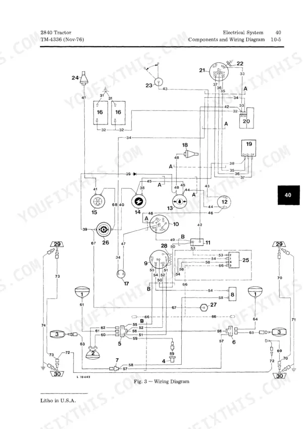
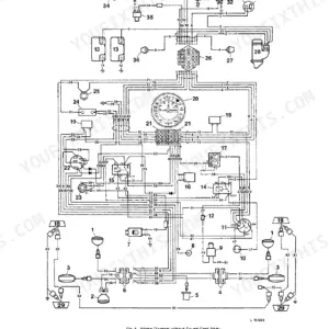
| Electrical System | 111-138 | Diagnosing Malfunctions, Components and Wiring Diagram, Starting Motor, Alternator and Regulator |
| Power Train | 139-202 | Engine Clutch and Clutch Linkage, Hi-Lo Shift Unit, Collar-Shift Transmission, Differential, Final Drives, PTO and PTO Clutch |
| Front Axle, Steering System, and Hydraulic Brakes | 203-226 | Front Axle, Steering System, Hydraulic Brakes |
| Hydraulic System | 227-288 | General Information, Diagnosing Malfunctions and Tests, Oil Reservoir, Filter, Valves and Oil Cooler, Hydraulic Pump and Transmission Oil Pump, Rockshaft |
| Miscellaneous | 289-298 | De Luxe Seat, Front and Rear Wheels, Roll Gard |
Quick Reference Specifications
| Specification | Value | Page |
|---|---|---|
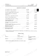
| Hydraulic pump delivery per pump shaft revolution | 39.5 cm³ (2.40 cu. in.) | p. 256 |
| Theoretical pump delivery per pump shaft revolution | 39.5 cm3 (2.40 cu.in.) | p. 256 |
| O.D. of pressure or return valves | 12.60 to 12.62 mm | p. 284 |
| O.D. of flow control valve | 19.00 to 19.02 mm | p. 284 |
| Resilience of Yellow springs at 41 mm (1.62 in.) length | 154 to 161 N (34.0 to 35.5 lb) | p. 257 |
| Resilience of Green springs at 41 mm (1.62 in.) length | 161 to 168 N (35.5 to 37.0 lb) | p. 257 |
| Valve leakage pressure | 103 bar (1500 psi) | p. 282 |
| Engine Cylinder Liner Bore | 102 mm (4.02 in.) | p. 6 |
| Engine Fast Idle Speed | 2660 rpm | p. 6 |
| Engine Crankcase Oil Capacity (including filter) | 11.5 L (3 U.S. gal.) | p. 15 |
| Hydraulic System Pressure | 155 bar (2250 psi) | p. 7 |
| Cylinder Head to Cylinder Block Torque | 130 Nm (95 ft-lb) | p. 47 |
John Deere 2840 Common Problems This Manual Covers
John Deere 2840 hydraulic system slow operation or no oil pressure to rockshaft and remote cylinders
Test hydraulic system pressure against 155 bar (2250 psi) from page 7. Before opening any line for the test, relieve all pressure, since the page 24 caution warns escaping fluid can penetrate skin. Tighten every connection and check hoses for damage before restarting. Then measure transmission oil pump delivery against the 40 L/min (10.5 gpm) minimum at 2500 rpm on page 257.
Manual Section: Hydraulic System Diagnosing MalfunctionsSelective control valve remote cylinder settles under load or won't stay in detent
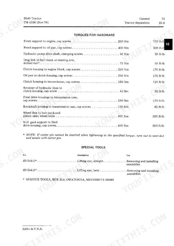
Test the selective control valve for leakage at 103 bar (1500 psi) per page 282, and do not remove valves unless necessary. Relieve all pressure before disconnecting remote lines, as the page 24 caution requires. If the housing comes apart, measure detent piston O.D. against 18.92 to 18.97 mm and pressure or return valves against 12.60 to 12.62 mm on page 284, then torque the cap to 50 Nm (35 ft-lb).
Manual Section: Selective Control Valve Diagnosing MalfunctionsEngine hard to start or will not start with fuel not reaching injection nozzles
Check that the fuel tank shut-off valve is open. Then inspect for a restricted fuel filter, clogged lines, and water, dirt or air in the fuel system, following the chart on page 92. Verify the shut-off knob is not stuck. Check the speed-control linkage, because the injection pump metering valve can stick closed. Test transfer pump pressure and injection timing next.
Manual Section: Fuel System Diagnosing Malfunctions p. 92Six-cylinder diesel engine overheats while working, with coolant temperature gauge running high
Check the coolant level. Clean the radiator core and side grille screens, then inspect the fan belt for slack or damage. Test the thermostat and radiator cap, and check for a limed-up cooling system or a failed water pump per pages 35 and 36. Verify engine timing and crankcase oil level. Check the cylinder head gasket if those pass.
Manual Section: Engine Diagnosing Malfunctions p. 35Engine oil pressure warning light comes on showing low oil pressure while running
Check the crankcase oil level and confirm the correct oil is in it. Never put additives in the crankcase (page 16). Test the oil pressure warning switch, which closes at 0.4 to 0.7 bar (5.5 to 10.5 psi) per page 119. If the switch and light check good, inspect the regulating valve adjustment, the oil pump and the bearing clearances listed on page 36.
Manual Section: Engine Diagnosing Malfunctions p. 36Alternator indicator light stays on with the engine running and batteries not charging
Check the fan belt for slipping and the battery terminals for looseness or corrosion. Run the engine at 1000 to 1400 rpm with a voltmeter on alternator B+ and ground; the reading should rise above 13 volts (page 113). At fast idle, verify output reaches 25 amps and the regulator limits at 14.0 to 14.6 volts (page 114). Never short alternator or regulator terminals with the engine running (page 117).
Manual Section: Electrical System Diagnosing Malfunctions p. 114Frequently Asked Questions
How do I diagnose low hydraulic pressure on a John Deere 2840?
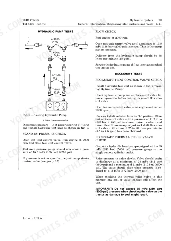
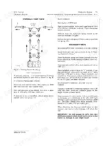
First relieve hydraulic system pressure, as the manual cautions that escaping fluid under pressure can penetrate the skin, then remove the 3/8 in. plug on the front right-hand side of the rockshaft housing. To diagnose low hydraulic pressure, connect a 0 to 250 bar (0 to 3550 psi) pressure gauge to the plug port on the front right-hand side of the rockshaft housing. Run the engine at 2000 rpm and check the stand-by pressure, which should be 15.5 mPa (155 bar) (2250 psi). p. 234
How do I bleed the hydraulic brakes on a John Deere 2840?
Attach a plastic bleed hose to the brake bleed screw on the final drive housing and insert the other end into the transmission filler hole. Open the bleed screw 3/4 turn, slowly depress the brake pedal, and allow it to return slowly until no air bubbles appear in the hose. Close the screw securely while the pedal is depressed. p. 223
What is the correct valve clearance for the John Deere 2840 engine intake and exhaust valves?
The valve clearance for both intake and exhaust valves on the John Deere 2840 engine is 0.35 mm (0.014 in.) for the intake valve and 0.45 mm (0.018 in.) for the exhaust valve, measured when the engine is hot or cold. p. 6
What is the torque specification for the cylinder head cap screws on the John Deere 2840?
The cylinder head cap screws should be tightened to 130 Nm (95 ft-lb). When installing, the screws should be dipped in oil. p. 47
What is the capacity of the engine crankcase including the filter?
The engine crankcase capacity, including the filter, is 11.5 liters (3 U.S. gallons). p. 15
How will I receive this John Deere 2840 Technical Manual?
You get a 298-page searchable PDF that downloads instantly after checkout. Open it on your laptop, tablet, or phone, and bring it right to the shop floor.
Is printing allowed for this John Deere 2840 Technical Manual?
Yes. Print the pages or sections you need for your own shop use. Any standard printer works.