Part of the John Deere Repair Manuals.
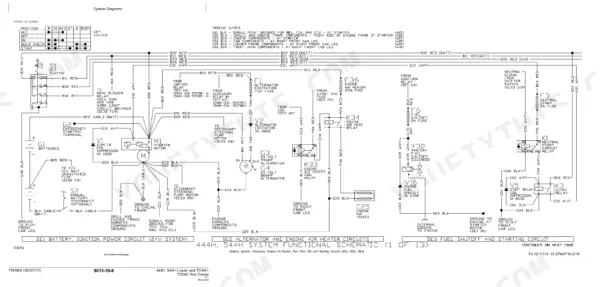
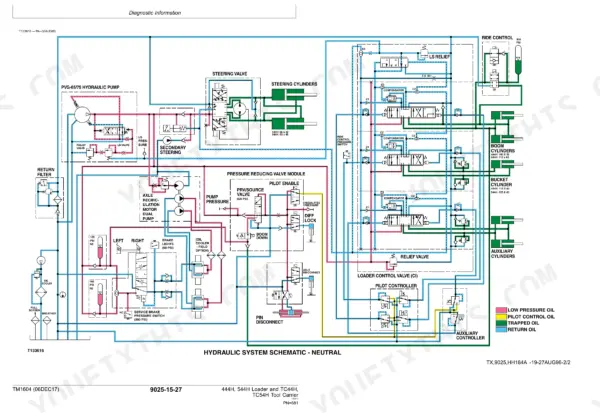
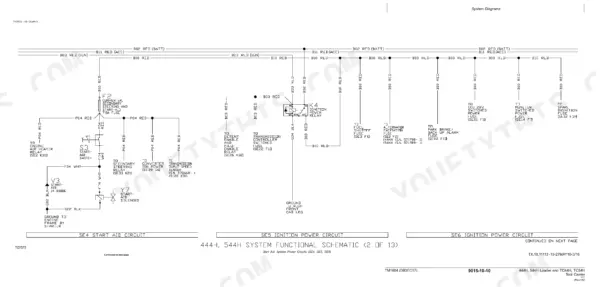
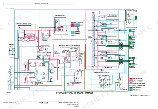
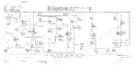
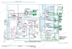
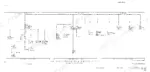
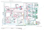
Your 544H just logged a transmission service code with a stockpile waiting, and TM1604, John Deere's 832-page technical manual for the H-Series loader and tool carrier family, lays out the diagnostics for all four variants, 444H through TC54H. Electrical work takes up nearly two-fifths of this John Deere 544H technical manual PDF, with wiring diagrams that trace each harness from the controllers to sensors such as the B28 and B29 torque converter speed pickups. Hydraulic schematics map the loader valve and bucket cylinder circuits, while theory of operation and diagnostic chapters cover the power train. Set the boom height kickout switch at 5 to 8 mm (0.197 to 0.315 in.) from its adjustable plate, and expect 17 to 21 ohms across a healthy control valve solenoid. Every hour it sits parked is tonnage you're not moving. Bookmarked and text-searchable, the file helps you isolate the failed component and order the right part the first time.
What's Inside This Manual
| System | Pages | Key Topics |
|---|---|---|
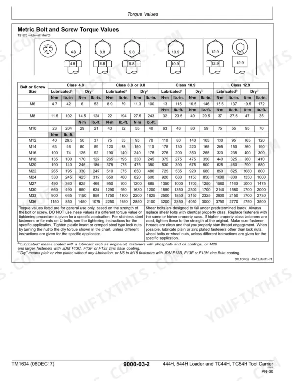
| General Information | 1-44 | Safety Information (Handle Fluids Safely, Avoid Fires, Prevent Battery Explosions) |
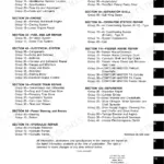
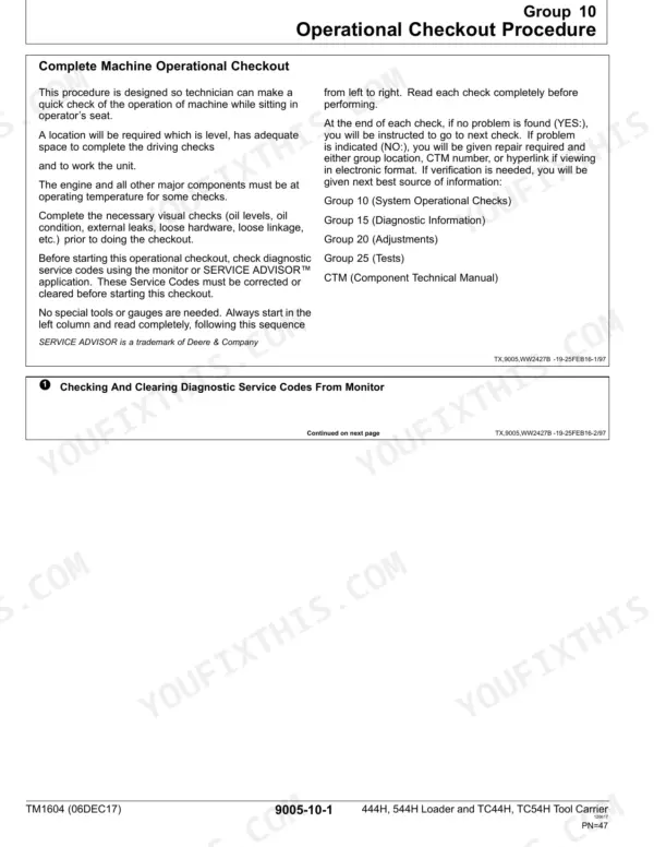
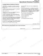
| Operational Checkout Procedure | 45-114 | Diagnostic Service Codes, Monitor Indicator, Transmission Controls, Brake System, Steering System, Cab Component |
| Engine | 115-144 | Theory of Operation, Diagnostic Information, Adjustments, Tests |
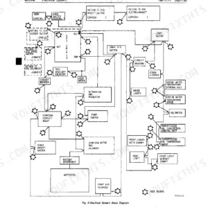
| Electrical System | 145-464 | System Information, System Diagrams, Sub-System Diagnostics |
| Power Train | 465-566 | Torque Converter Operation, Transmission Operation, Transmission Test Points, Axle Breather Test |
| Hydraulic System | 567-762 | Hydraulic Pump Control, Steering Valve Operation, Boom Raise Operation, Loader Hydraulic System |
| Heating and a/C | 763-832 | Theory of Operation, System Operational Checks, Diagnostic Information, Adjustments, Tests |
Quick Reference Specifications
| Specification | Value | Page |
|---|---|---|
| All Models | ||
| Torque Converter Input Speed Sensor (B28) Normal Operating Range | 900—2250 rpm | p. 333 |
| Torque Converter Output Speed Sensor (B29) Normal Operating Range | 0—2250 rpm | p. 333 |
| Control Valve Solenoid Resistance | 17—21 ohms | p. 360 |
| Minimum oil to add to reservoir for wash out | 19 L (5 gal) | p. 711 |
| Switch and Adjustable Plate Clearance (Boom Height Kickout) | 5—8 mm (0.197— 0.315 in.) | p. 712 |
| Switch and Adjustable Plate Clearance (Return-To-Carry) | 5—8 mm (0.197— 0.315 in.) | p. 713 |
| Ride Control Hydraulic Pressure | 0 kPa, 0 bar, 0 psi | p. 717 |
| Ride Control Accumulator Gas Charge Pressure | 1930—2210 kPa, 19.3—22.1 bar, 280—320 psi | p. 718 |
| Hydraulic Oil Temperature | 40 ± 6°C (100 ± 10°F) | p. 760 |
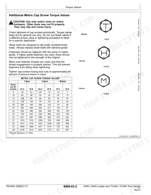
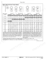
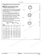
| ROPS Mounting Bolts Torque | 620 ± 120 N·m (457 ± 88 lb-ft) | p. 29 |
| 444H, TC44H | ||
| 444H/TC44H Fuel Tank Capacity | 180 L (48 gal) | p. 23 |
| 544H, TC54H | ||
| 544H/TC54H Fuel Tank Capacity | 246 L (65 gal) | p. 28 |