Part of the John Deere Repair Manuals.
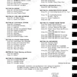
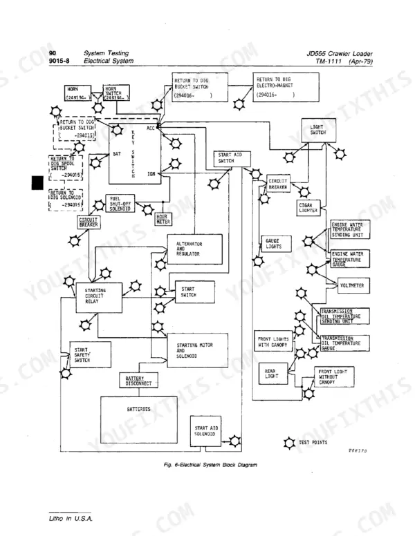
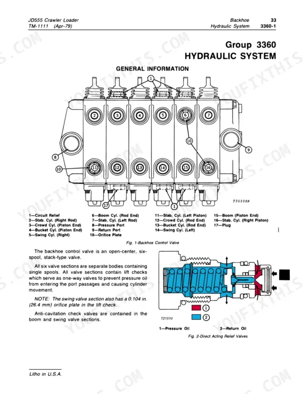
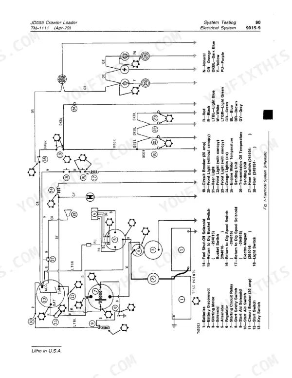
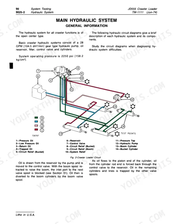
What a John Deere JD555 crawler loader should measure, from track sag to axle shaft end play, is settled by one book: the John Deere JD555 technical manual PDF, TM-1111, running 687 pages. Section 90 System Testing takes up nearly a fifth of it and works through engine, electrical, hydraulic, power train and winch diagnosis in order, while wiring diagrams trace the charging circuit and harness and hydraulic schematics map oil routing through the backhoe and test circuits. Teardown coverage runs from rollers and idler springs through the torque converter, power shift clutch, engine and winch drive, then on to loader frames, buckets and loader hydraulics. Set track sag at 7/8 to 1-1/8 inch (22 to 29 mm) and hold axle shaft end play to 0.001 to 0.005 inch (0.03 to 0.13 mm). A bearing job stalls on one missing clearance. Buy this bookmarked, text-searchable PDF once and you keep it for the life of your JD555.
What's Inside This Manual
| System | Pages | Key Topics |
|---|---|---|
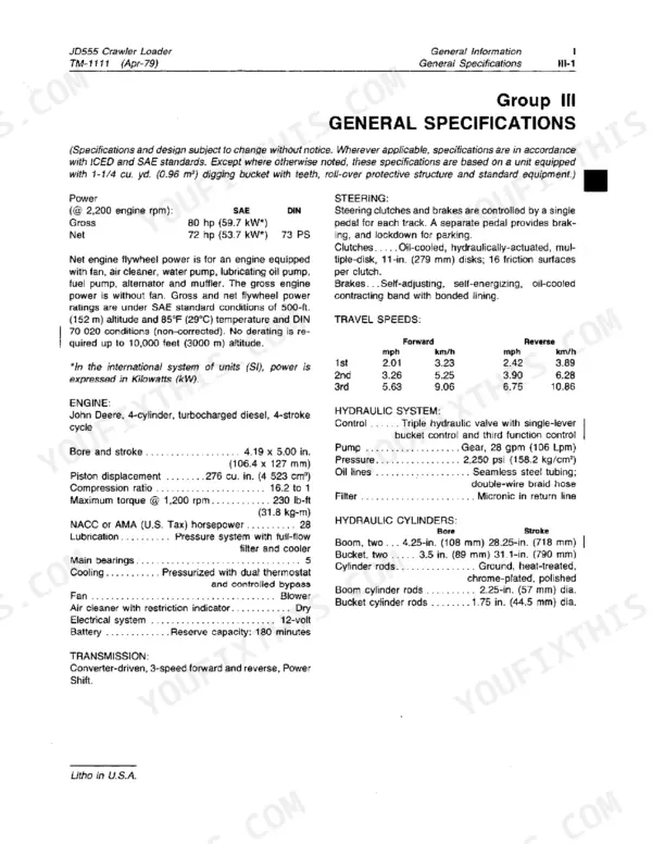
| General Information | 1-58 | Introduction and Safety Information, General Specifications, Predelivery, Delivery, And After-Sale Services |
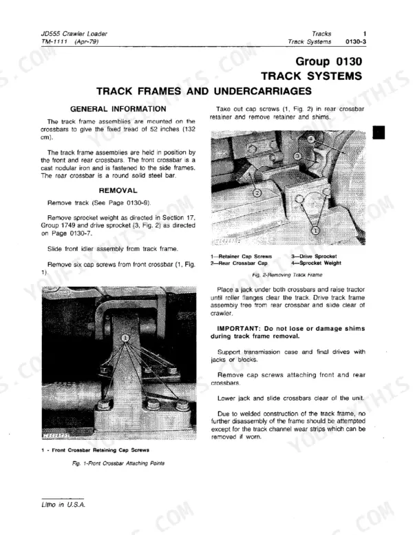
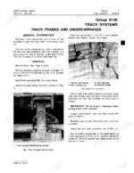
| Tracks | 59-90 | Track Systems, Drive Sprockets, Chains and Shoes, Rollers, Idlers and Idler Springs |
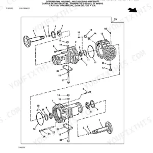
| Axles and Suspension Systems | 91-122 | Drive Axle Housing, Bevel Drive, Axle Shaft, Bearings and Reduction Gears |
| Transmission | 123-176 | Controls, Housings and Covers, Gears, Shafts, Bearings and Power Shift Clutch, Transmission Hydraulics |
| Engines | 177-291 | Removal and Installation, Crankshaft and Main Bearings, Camshaft and Valve Actuating Means, Connecting Rods and Pistons, Cylinder Block, Engine Oiling System, Turbocharger |
| Engine Auxiliary Systems | 292-305 | Cold Weather Starting Aids, Engine Cooling Systems, Intake System, External Fuel Supply Systems |
| Torque Converter | 306-325 | Converter Housing and Cover, Converter Turbine, Gears and Shafts, Converter Hydraulics |
| Steering Systems | 326-335 | Power Steering, Steering Valve |
| Equipment Attaching | 336-341 | Drawbar |
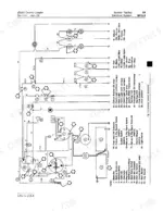
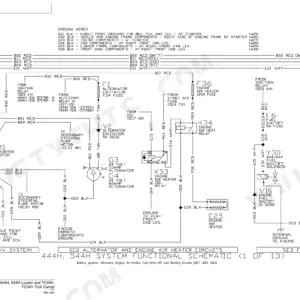
| Electrical Systems | 342-385 | Batteries, Supports and Cables, Alternator, Regulator and Charging System Wiring, Lighting System, Wiring Harness and Switches |
| Crawler Main Frame | 386-395 | Side Frames, Frame Bottom Guards, Chassis Weights |
| Operator's Station | 396-409 | Safety Equipment, Comfort and Convenience Items, Operator Enclosure, Seat |
| Sheet Metal | 410-415 | Hood or Engine Enclosure, Grille and Grille Housing |
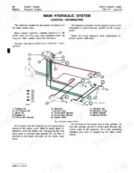
| Main Hydraulic System | 416-425 | Hydraulic System |
| Winch | 426-453 | Controls Linkage, Winch Housing and Mounting Structure, Winch Drive and Clutches, Winch Hydraulic System |
| Loader | 454-487 | Buckets, Forks, Loader Frames, Loader Hydraulics |
| Backhoe | 488-525 | Bucket, Controls Linkage, Frames, Hydraulic System |
| Log Arch | 526-529 | Arch Frames |
| Winch Drive | 530-533 | Gears, Shafts and Bearings |
| Ground Conditioning Tool | 534-545 | Teeth and Shanks, Frame, Hydraulic System |
| System Testing | 546-673 | Diagnosis Steps, Engine Testing, Electrical System Testing, Hydraulic System Testing, Power Train Testing, Winch System Testing |
| Index | 674-679 | Alphabetical Index of Components and Procedures |
| Blank Pages | 680-687 |
Quick Reference Specifications
| Specification | Value | Page |
|---|---|---|
| Proper track tension sag | 7/8 to 1-1/8 inch (22 to 29 mm) | p. 36 |
| Maximum grease gun capacity for track adjustment | 8,000 psi (562 kg/cm²) | p. 36 |
| Steering brake pedal travel | 2.5 in. (63.5 mm) | p. 52 |
| Axle shaft end play | 0.001 to 0.005-inch (0.03 to 0.13 mm) | p. 109 |
| Rolling torque with new bearings | 90 to 115 lb-in (1.0 to 1.3 kg-m) | p. 109 |
| Steering clutch housing oil capacity | approximately 3 gallons (11.4 L) per housing | p. 114 |
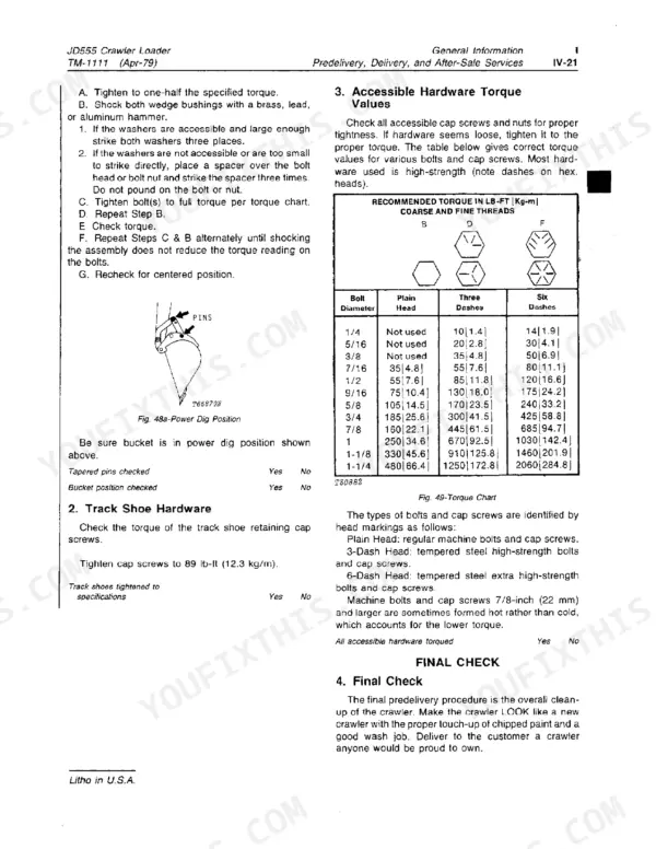
| Cap screw torque | 10 lb-ft (14 Nm) | p. 121 |
| Bypass valve spring (15) free length | 2.39-inch (60.7 mm) | p. 169 |
| Bypass valve spring (15) test length | 1.21-inch (30.7 mm) when compressed with 5.54 lbs. (2.5 kg) | p. 169 |
| Clamp plate screw tightening torque | 15-17 lb-ft (2.07-2.35 kg/m) | p. 317 |
| Steering clutch pressure test | With steering clutch released, shift to forward. Forward pack should go to 60 to 110 psi (4 to 8 kg/cm²) and then to 250 to 280 psi (18 to 20 kg/cm²) on a rate of rise. | p. 627 |
| Engine Gross Power | 80 hp (59.7 kW) | p. 15 |