Part of the John Deere Repair Manuals.
Both the 762B and 862B scrapers fall under TM1490, the John Deere 762B repair manual PDF, and its 769 pages give model-specific values where the two machines differ. Repair procedures and exploded views work through the drive axles and differential, the transmission and power shift clutch, the torque converter, the steering and service brake hydraulics, and the conveyor, gearbox and controls linkage of the elevating device. A final section shows you the alignment, differential lifting and axle jacking tools a dealer fabricates. Fill a 762B transmission with 49 L (13 gal) of oil after a filter change, or an 862B with 71 L (19 gal), then torque the planetary pack-to-case cap screws to 115 N·m (85 lb-ft). Bookmarks and a text layer let you jump straight to the right section, and every page prints cleanly as a working copy to keep open while you rework the park brake control linkage.
What's Inside This John Deere 762B, 862B Repair Manual
| System | Pages | Key Topics |
|---|---|---|
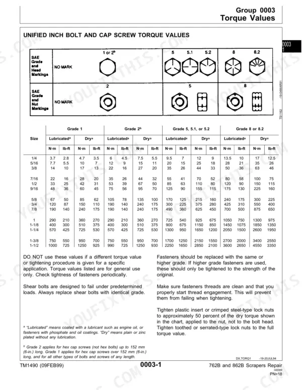
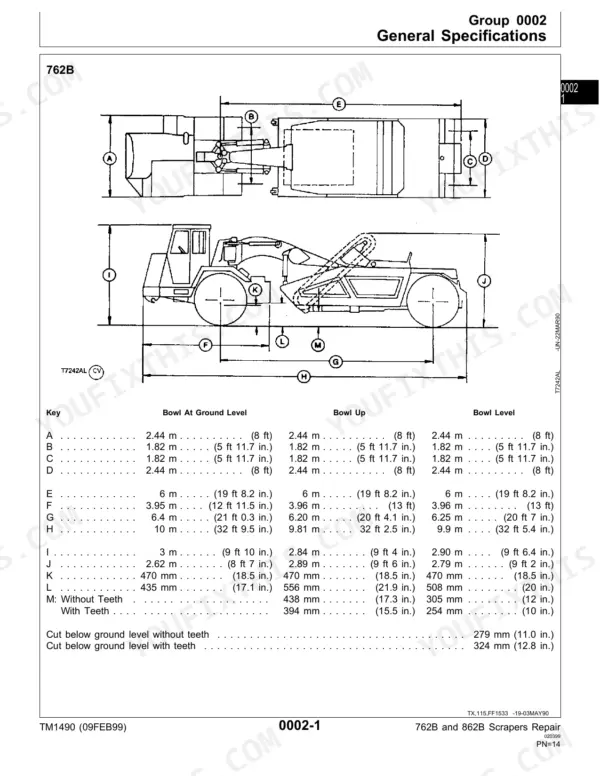
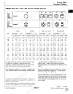
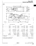
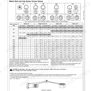
| General Information | 1-29 | Safety, General Specifications, Torque Values, Fuels and Lubricants |
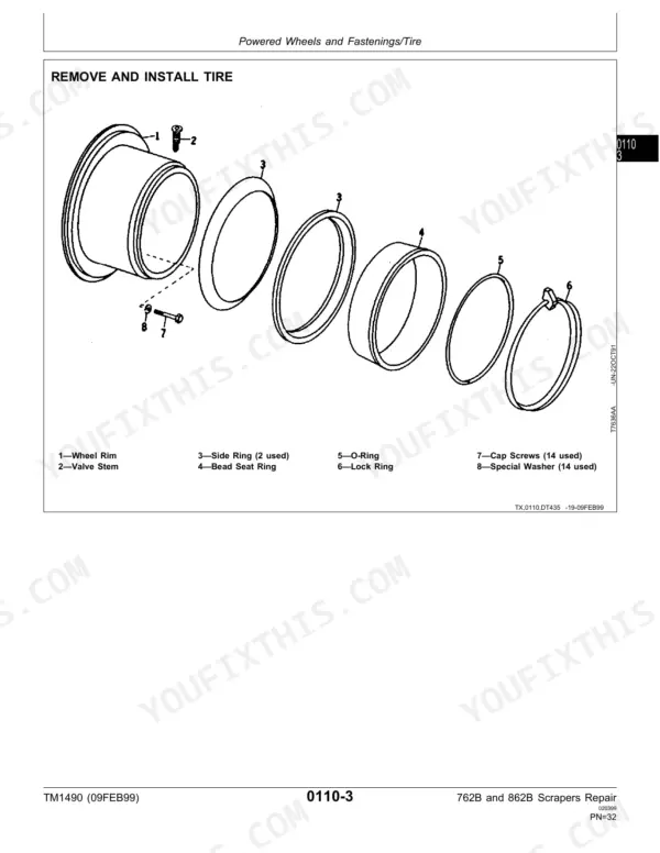
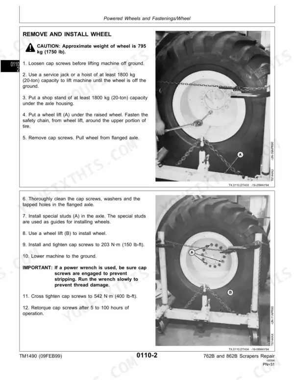
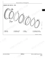
| Wheels | 30-35 | Powered Wheels and Fastenings |
| Axles and Suspension System | 36-123 | Drive Axle Housing and Support, Differential or Bevel Drive, Non-Powered Wheel Axles, Axle Shaft, Bearings and Reduction Gears |
| Transmission | 124-235 | Removal and Installation, Controls Linkage, Gears, Shafts, Bearings and Power Shift Clutch |
| Engine | 236-283 | Removal and Installation |
| Engine Auxiliary Systems | 284-327 | Cold Weather Starting Aids, Cooling Systems, Speed Controls, Intake System, External Exhaust System, External Fuel Supply Systems |
| Torque Converter | 328-367 | Housing and Cover, Converter Turbine, Gears, And Shaft |
| Dampener Drive | 368-369 | Elements |
| Steering System | 370-399 | Hydraulic System |
| Service Brakes | 400-427 | Active Elements, Hydraulic System |
| Park Brake | 428-437 | Active Elements, Control Linkage |
| Miscellaneous Vehicle | 438-445 | Central Lubrication Systems |
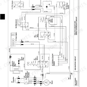
| Electrical Systems | 446-469 | Batteries, Supports and Cables, Alternator, Regulator and Charging System Wiring, Lighting System, Wiring Harness and Switches, System Controls |
| Frames | 470-481 | Frame Installation |
| Operator's Station | 482-523 | Operator Enclosure, Seat and Seat Belt, Heating and Air Conditioning |
| Main Hydraulic System | 524-539 | Radial Piston Pump, Main Hydraulic Pump, Pump Drive Shaft, Tandem Pump, Triple Pump, Hydraulic Filter |
| Scraper and Haulage Device | 540-591 | Blades or Cutting Edges, Hydraulic System |
| Conveyor and Elevating Device | 592-711 | Conveyor or Mast, Controls Linkage, Gearbox, Hydraulic System |
| Dealer Fabricated Tools | 712-757 | Alignment Tool, Differential Lifting Tool, Axle Jacking Tool |
Quick Reference Specifications
| Specification | Value | Page |
|---|---|---|
| 762B | ||
| Transmission oil with filter change | 49 L (13 gal) | p. 17 |
| Turbine-to-drive housing height | 19—20.5 mm (0.75—0.81 in.) | p. 333 |
| Cooling System Capacity | 34 L | p. 17 |
| Fuel Tank Capacity | 273 L | p. 17 |
| 862B | ||
| Transmission Oil Capacity | 71 L | p. 17 |
| Cooling System Capacity | 49 L | p. 17 |
| All Models | ||
| Planetary Pack-to-Case Cap Screws Torque | 115 N·m (85 lb-ft) | p. 150 |
| Planetary Brake Housing Cap Screws Torque | 115 N·m (85 lb-ft) | p. 150 |
| Cap screw torque for C1 clutch | 47 N·m (35 lb-ft) | p. 161 |
| Turbine height above edge of housing | 19-20.5 mm (0.75-0.81 in.) | p. 341 |
| Output shaft bearing retainer-to-case cap screw torque | 40 N·m (30 lb-ft) | p. 362 |
John Deere 762B, 862B Common Problems This Manual Covers
John Deere 762B 862B scraper axle housing reinstalled on differential case, axle shaft will not turn
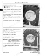
Remove the cap screws and pull the axle housing, keeping the brake backing plate and disk from falling as page 43 warns. A shaft that will not turn means the brake disk is assembled incorrectly. Reseat the disk, fit a new gasket, install the dowel pin small end out, run two cap screws finger tight, then check that the axle shaft turns.
Manual Section: Drive Axle Housing and Support p. 43Transmission planetary brake pack does not operate during the compressed air check after rebuild
Check brake pack operation with compressed air at 345 to 552 kPa (50 to 80 psi) following page 172. Before final assembly, measure spring (H): 60 mm (2.36 in.) free length and 36 mm (1.42 in.) at 156 N (35 lb) on page 165. Measure spring (K): 31 mm (1.22 in.) free and 20 mm (0.79 in.) at 156 N on page 166. Tighten cap screws to 115 N·m (85 lb-ft).
Manual Section: Transmission p. 172Torque converter turbine height above housing edge out of specification at reassembly
Measure turbine height above the edge of the housing following page 341. Confirm 19.0 to 20.5 mm (0.75 to 0.81 in.); page 358 repeats the same check. Do not close up the converter until the reading falls inside that window. Then torque cap screw (2) to 87 N·m (64 lb-ft) and cap screw (7) to 30 N·m (22 lb-ft) per page 342.
Manual Section: Torque Converter p. 341Fan shroud sitting out of vertical alignment around the fan after radiator installation
Wait until the top radiator tank is cool to the touch before draining coolant, as page 291 warns. Lift the radiator with JT01748 lift brackets and a hoist. It weighs about 89 kg. Add or remove shims between the radiator mount plate and engine frame to set the shroud vertically per page 292. Then fill the cooling system and check for leaks.
Manual Section: Engine Auxiliary Systems p. 292Engine intake air cleaner element still loaded with dust after the first cleaning attempt
Blow the element out with compressed air reduced below 210 kPa (2.1 bar) (30 psi). Direct the air up and down the pleats from inside to outside, following page 308. Clear bystanders from the area, guard against flying chips, and wear personal protection equipment including eye protection. Then reinstall the element.
Manual Section: Engine Auxiliary Systems p. 308Cold weather coolant heater element sheath burst or damaged in the engine block
Shut off the engine. Remove the filler cap only when it is cool enough to touch with bare hands, loosening it to the first stop to relieve pressure (page 285). Drain the cooling system, remove the wiring lead, loosen the nut and pull the heater element from the block. Replace parts as necessary. Never plug the heater in unless the element is immersed in coolant, and use a heavy-duty grounded cord.
Manual Section: Engine Auxiliary Systems p. 285Frequently Asked Questions
What is the torque specification for the axle housing-to-differential case cap screws on a 762B or 862B?
The torque specification for the axle housing-to-differential case cap screws is 339 N·m (250 lb-ft). It is required to cross tighten these screws. p. 400
What is the procedure for checking the rolling drag torque of the differential housing on a 762B or 862B?
Rotate the differential a minimum of two times and check the rolling drag torque. The specification for both models is 2.3–4.5 N·m (20–40 lb-in). p. 66
What is the torque specification for the engine mount isolator nut on the John Deere 762B, 862B?
The torque specification for the engine mount isolator nut is 603 N·m (445 lb-ft). p. 312
What is the procedure for bleeding the brake hydraulic system?
Two service technicians are required. Install a bleed hose on the bleed screws to prevent oil from spraying. Destroke the main hydraulic pump by turning the destroke screw clockwise until it stops. Allow oil and air to flow into a container until no more air bubbles are seen (approximately two minutes). Close the bleed screw while the brake pedal is depressed. p. 426
Is this John Deere 762B manual a PDF I download?
One searchable PDF covering 769 pages, delivered instantly. No disc, no shipping, no waiting on the post.
Am I able to print pages from this John Deere 762B manual?
Yes. Print a single page or a chapter for your own shop use, on letter or A4.