Part of the John Deere Repair Manuals.
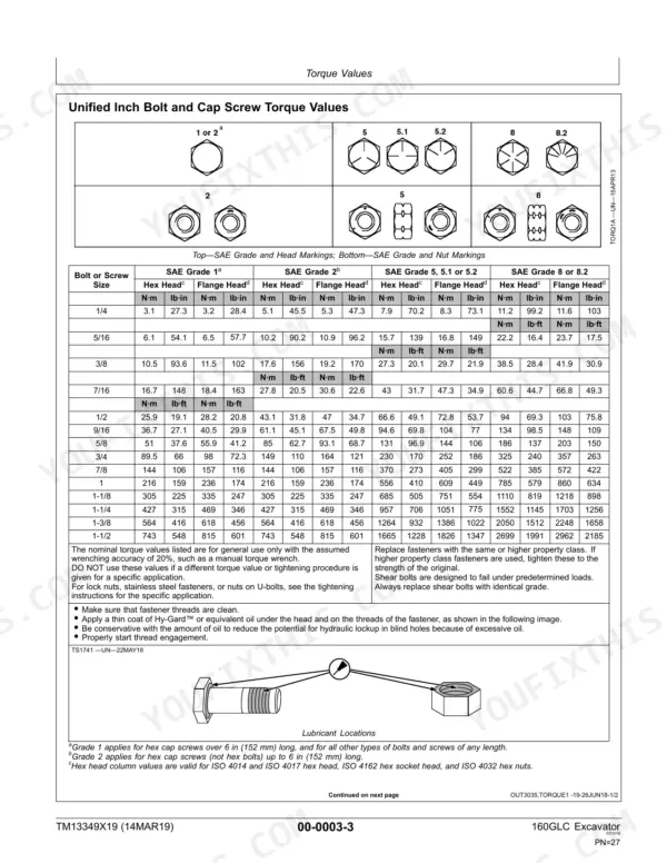
Factory publication TM13349X19 is John Deere's own 462-page repair book for the 160GLC excavator, and this John Deere 160GLC repair manual PDF reproduces it whole. Undercarriage work comes first: track rollers, carrier rollers, track chain, sprocket, front idler and the track adjuster with its recoil spring, then travel gear case, travel motor and park brake. Later sections cover engine removal, cooling, exhaust and fuel supply, the flex coupling, chassis weights, cab heating and air conditioning, buckets, excavator hydraulics and swing drive, plus dealer fabricated tools like the travel gear case nut wrench. Rig for roughly 170 kg (375 lb) when lifting pumps 1 and 2. Torque cap screw (41) to 538 N·m (397 lb·ft). Perhaps you are ordering a replacement front idler and want its fitting procedure in hand first. Bookmarks and searchable text lead straight to the Tracks section, so you can fit that idler and check roller pressure at 82 to 138 kPa (12 to 20 psi).
What's Inside This John Deere 160GLC Repair Manual
| System | Pages | Key Topics |
|---|---|---|
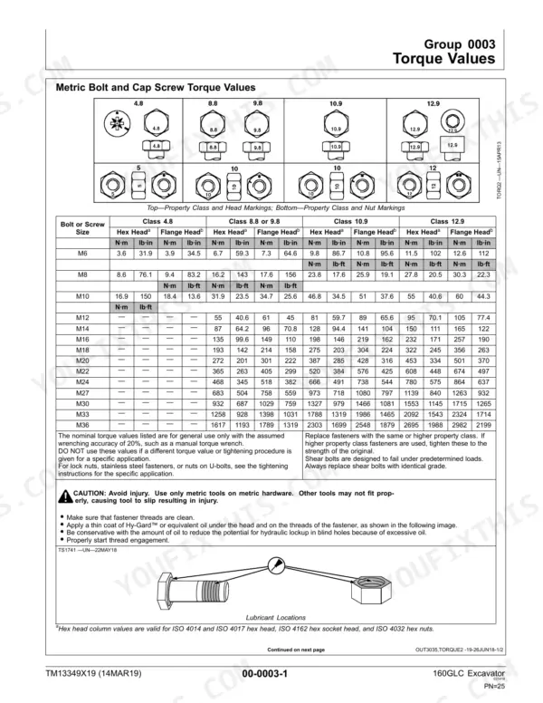
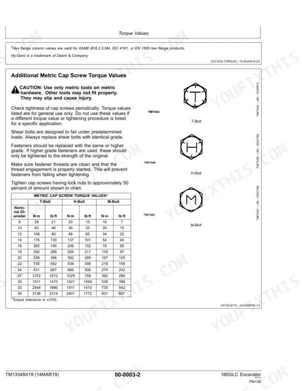
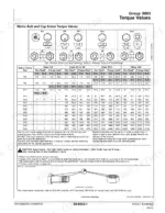
| General Information | 7-46 | Safety, Torque Values |
| Tracks | 47-84 | Track System, Track Roller, Track Carrier Roller, Track Chain, Sprocket, Front Idler, Track Adjuster and Recoil Spring |
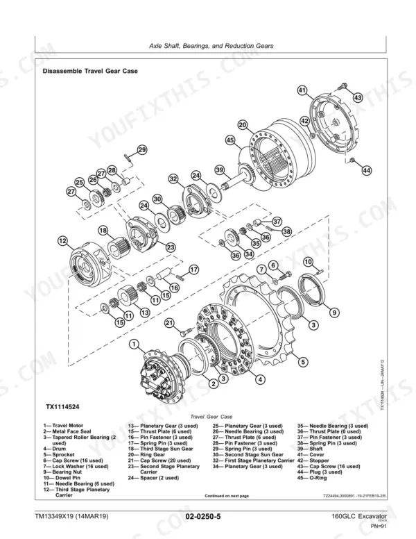
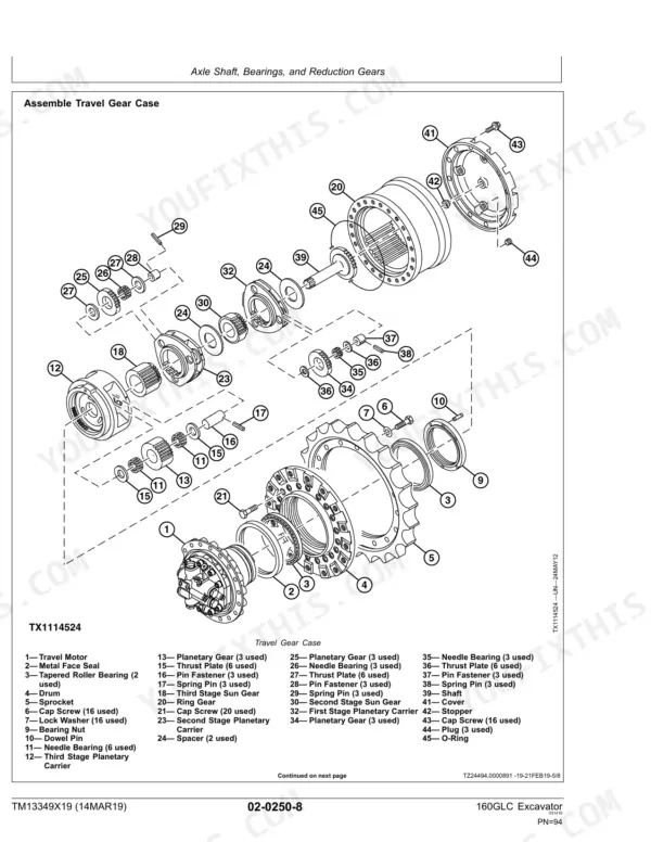
| Axles, Differentials, and Suspension Systems | 85-108 | Axle Shaft, Bearings, And Reduction Gears, Hydraulic System, Travel Gear Case, Travel Motor, Park Brake |
| Engine | 109-122 | Removal and Installation, Engine Remove and Install |
| Engine Auxiliary System | 123-168 | Cooling Systems, External Exhaust Systems, External Fuel Supply Systems |
| Damper Drive (Flex Coupling) | 169-172 | Elements |
| Frame or Supporting Structure | 173-178 | Frame Installation, Chassis Weights |
| Operator's Station | 179-240 | Removal and Installation, Operator Enclosure, Seat and Seat Belt, Heating and Air Conditioning |
| Sheet Metal and Styling | 241-244 | Hood or Engine Enclosure |
| Excavator | 245-392 | Buckets, Frames, Hydraulic System |
| Swing or Pivoting System | 393-436 | Mechanical Drive Elements, Hydraulic System |
| Dealer Fabricated Tools | 437-462 | Lift Bracket, Track Recoil Spring Disassembly and Assembly Tool, Travel Gear Case Nut Wrench, Holding Bar, Center Joint Lifting Tool, Pump Support |
Quick Reference Specifications
| Specification | Value | Page |
|---|---|---|
| Track Roller Pressure | 82—138 kPa (0.8—1.4 bar, 12—20 psi) | p. 53 |
| Pump 1 and 2 Weight (approximate) | 170 kg (375 lb) | p. 111 |
| Cap Screw (41) Torque | 538 N·m (397 lb·ft) | p. 111 |
| Lock Nut Torque | 50 N·m (37 lb·ft) | p. 136 |
| Fuel Tank Capacity (approximate) | 285 L (75 gal) | p. 165 |
| Fuel Tank Weight (approximate without fuel) | 132 kg (291 lb) | p. 165 |
| 100-Pin Connector (X3) Cap Screw Torque | 10 N·m (89 lb·in) | p. 181 |
| Plug-to-Housing Torque | 25 N·m (221 lb·in) | p. 293 |
| 160GLC Excavator Weight (approximate) | 17 945 kg | p. 49 |
| Track Roller Weight (approximate) | 35 kg | p. 49 |
| Hydraulic Oil Tank Capacity | 125 L | p. 87 |
| Travel Gear Case Capacity | 6.8 L | p. 87 |
John Deere 160GLC Common Problems This Manual Covers
John Deere 160GLC track adjuster will not release track tension before track roller removal
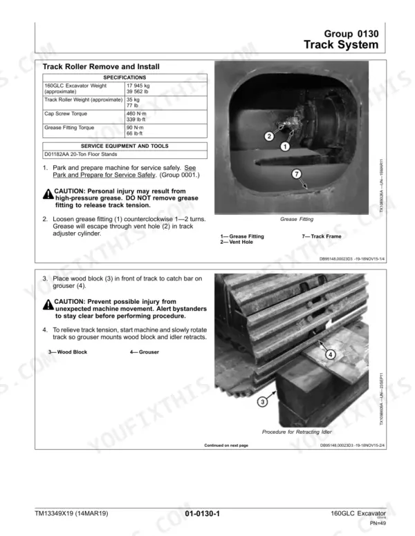
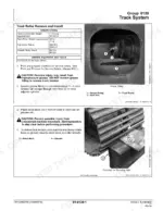
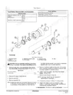
Loosen the grease fitting counterclockwise 1 to 2 turns and let grease escape through the vent hole. Never remove the fitting; page 49 warns of high-pressure grease. Alert bystanders, block the grouser with wood, and slowly rotate the track so the idler retracts. Raise the track with the boom-to-arm angle held at 90 to 110° (page 50), lower onto stands, and lift the 35 kg roller with a proper device.
Manual Section: Track System Repair p. 49Hydraulic pump drive and driven gear backlash beyond limit of use in pump drive gear case
Stop the engine and relieve system pressure before disconnecting any hydraulic line, as the caution on page 88 requires. Measure pump drive and driven gear backlash following page 271: nominal is 0.68 mm, limit of use 1.50 mm. Replace gears past the limit. Refill the pump drive gear case with 1.0 L of oil and torque the fill plug to 40 N·m per page 282.
Manual Section: Hydraulic System Repair p. 271Hydraulic pump pistons loose in cylinder block bores and drive shaft sockets at rebuild
Measure cylinder block bore-to-piston clearance against 0.043 mm nominal and 0.080 mm limit of use, and piston-to-drive shaft socket play against 0.058 mm nominal and 0.400 mm limit, both on page 280. Check piston-to-connecting rod play on page 281 against 0.150 mm nominal and 0.400 mm limit. Replace parts past limit, then torque cylinder head-to-pump housing cap screws to 110 N·m.
Manual Section: Hydraulic System Repair p. 280Pump servo piston worn in cylinder head bore and servo piston pin worn in valve plate bore
Measure servo piston-to-cylinder head bore clearance against 0.079 mm nominal and 0.200 mm limit of use following page 281. Check servo piston pin-to-valve plate bore clearance against 0.051 mm nominal and 0.300 mm limit on page 282. Replace worn parts, then torque the servo piston set screw and pin to 35 N·m and the regulator-to-pump housing cap screws to 50 N·m.
Manual Section: Hydraulic System Repair p. 281Travel gear case and motor assembly removal with travel motor hydraulic hoses still under pressure
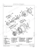
Stop the engine and relieve system pressure before disconnecting or connecting hoses, as the caution on page 88 requires. Tag and disconnect the hydraulic hoses, then cap and plug every opening. Support the assembly with the DF1063 Lift Bracket and DFT1130 Adapter on an appropriate lifting device (page 89). On install, torque assembly cap screws to 630 N·m and fill the gear case with 6.8 L per page 87.
Manual Section: Travel Gear Case Repair p. 87Frequently Asked Questions
What is the torque specification for the cap screws on the 160GLC excavator track roller?
The torque specification for the cap screws on the 160GLC excavator track roller is 460 N·m (339 lb·ft). p. 49
What is the capacity of the engine oil (SAE 30) for the track roller on the John Deere 160GLC?
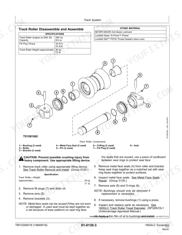
The track roller has an engine oil (SAE 30) capacity of 260 mL (8.8 oz). p. 51
What is the torque spec for the grease fitting on the track adjuster of the John Deere 160GLC?
The grease fitting on the track adjuster should be tightened to a torque of 90 N·m (66 lb·ft). p. 49
What is the procedure for relieving track tension on the 160GLC excavator?
To relieve track tension, loosen the grease fitting (1) counterclockwise 1—2 turns. Grease will escape through the vent hole (2) in the track adjuster cylinder. CAUTION: Personal injury may result from high-pressure grease. DO NOT remove the grease fitting to release track tension. p. 49
What is the torque specification for the cap screws on the John Deere 160GLC travel gear case and motor assembly?
The cap screws for the travel gear case and motor assembly must be tightened to 630 N·m (465 lb·ft). p. 87
What format is this John Deere 160GLC manual in?
Immediate download of the complete 462-page searchable Repair Manual. Access it on any device, from a laptop at your desk to a phone in the field.
Can I print this John Deere 160GLC manual?
Yes. Print a chapter or just the pages for the job at hand, for use in your own shop. Any home or office printer works.