
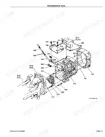
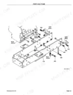
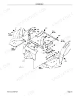
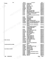
Part of the Kubota Parts Manuals.
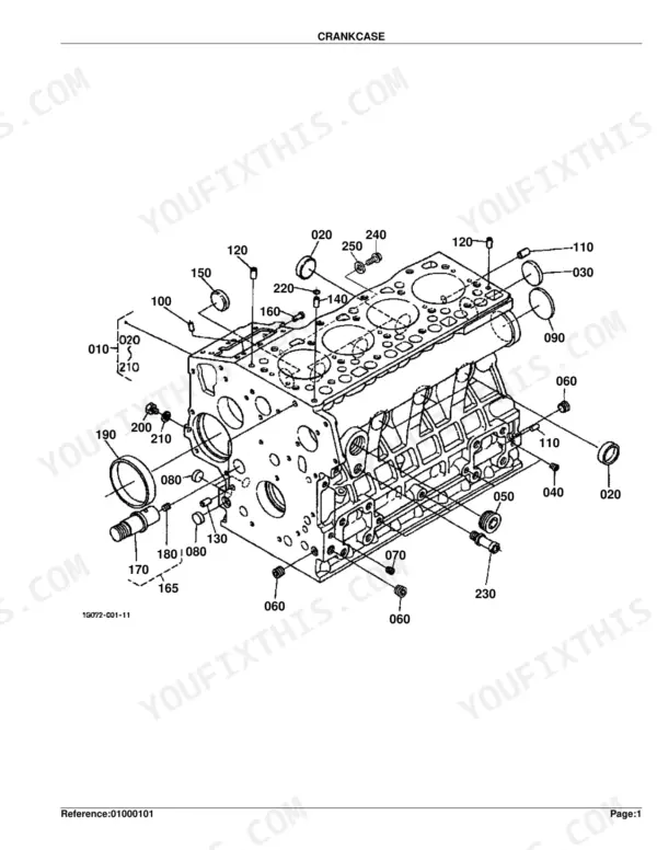
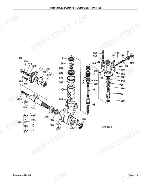
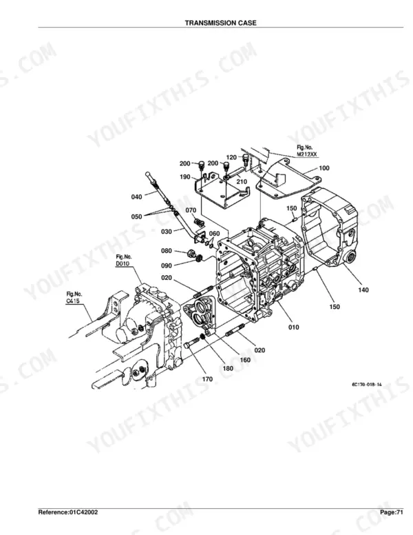
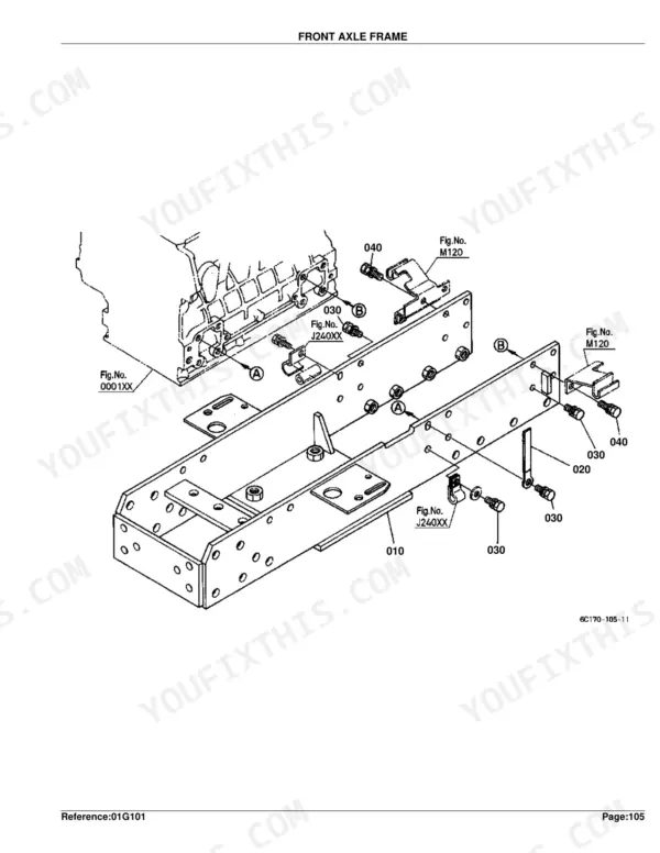
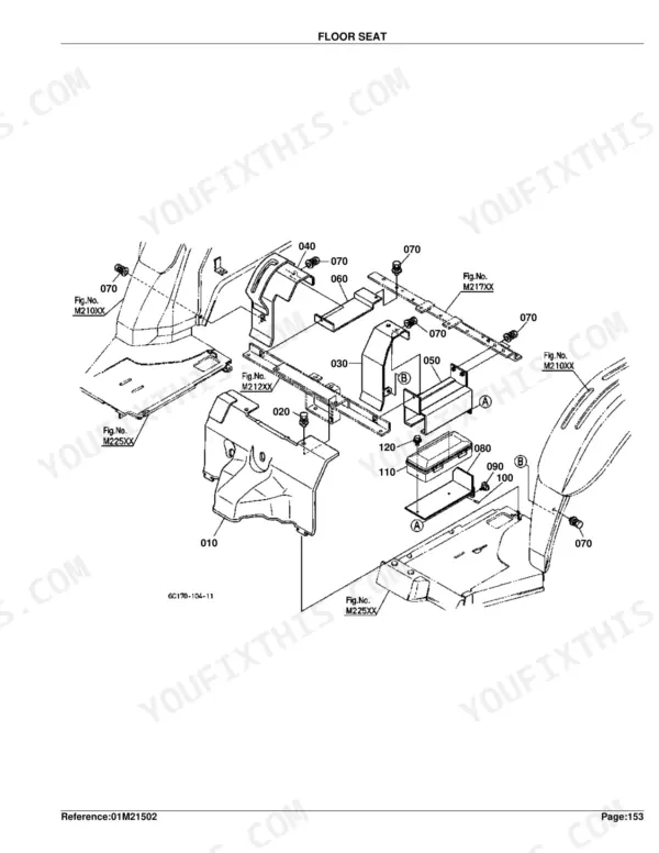
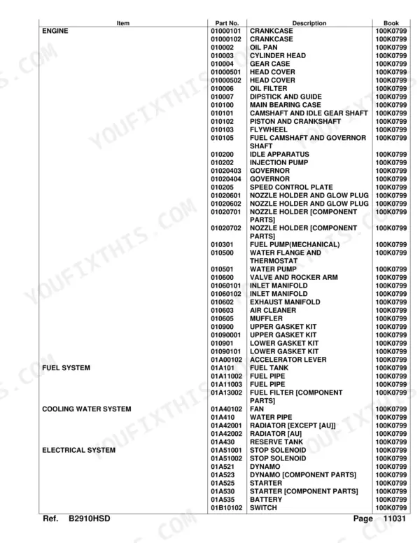
This is the factory parts catalog for the Kubota B2910HSD compact diesel tractor. It presents every assembly as an exploded diagram matched to Kubota part numbers, quantities, and serial-number ranges, covering the engine, fuel and cooling systems, electrical wiring, clutch, hydrostatic transmission, axles, brakes, steering, and body panels.
Across 404 pages of illustrated breakdowns you can pinpoint the exact component before ordering, use the interchangeability notes to handle superseded numbers, and confirm a part suits your serial range. It is the reference to keep next to a repair when you are rebuilding the HST, sourcing engine internals, or replacing gaskets and seals.
Delivered as a downloadable PDF you can read on a phone, tablet, or computer, or print the individual diagram pages you need for the bench.
What's Inside This Kubota B2910HSD Parts Manual
| System | Pages | Key Topics |
|---|---|---|
| Clutch & Transmission | Clutch, Clutch Rod, Clutch Pedal, Clutch Housing, Transmission Case, Clutch Shaft, HST, 2Nd Shaft, 3Rd Shaft, 4Th Shaft, Cruise Control Clutch, Neutral Holder Link, HST Release Arm, Range Gear Shift Lever, PTO Gear Shift Lever | |
| Fuel System | Fuel Camshaft and Governor Shaft, Idle Apparatus, Injection Pump, Governor, Speed Control Plate, Nozzle Holder and Glow Plug, Nozzle Holder, Fuel Pump, Air Cleaner, Accelerator Lever, Fuel Tank, Fuel Pipe, Fuel Filter, Stop Solenoid, Speed Control Pedal | |
| Cooling System | Water Flange and Thermostat, Water Pump, Fan, Water Pipe, Radiator, Reserve Tank | |
| Engine | Crankcase, Oil Pan, Cylinder Head, Gear Case, Head Cover, Oil Filter, Dipstick and Guide, Main Bearing Case, Camshaft and Idle Gear Shaft, Piston and Crankshaft, Flywheel, Valve and Rocker Arm, Inlet Manifold, Exhaust Manifold, Muffler, Upper Gasket Kit | |
| Electrical System | Dynamo, Starter, Battery, Switch, Panel Board, Hazard Light, Tail Light, Winker Lamp, Electrical Wiring, Alternator Kit, Alternator, Warking Light Kit | |
| PTO | PTO Shaft, Mid PTO, PTO Protector | |
| Rear Axle, Differential & Brakes | Rear Axle Case, Rear Differential, Rear Axle, Brake, Brake Rod, Parking Brake Lever, Brake Pedal, Differential Lock Pedal, Front Axle Case, Differential Gear Shaft, Rear Wheel | |
| Front Axle & Steering | Propeller Shaft, Front Wheel Propeller Shaft, Front Wheel Drive Lever, Front Axle Frame, Front Differential, Front Axle, Front Drive Shaft, Drag Link, Tie Rod, Steering Handle, Steering Post, Front Wheel, Power Steering Hose Kit | |
| Hydraulics & 3-Point Hitch | Hydraulic Control Lever, Hydraulic Pump, Hydraulic Oil Line, Hydraulic Cylinder, Feed Back Lever, Control Valve, Relief Valve, 3-Point Linkage 2, Lower Link, 3-Point Linkage 1, Hitch/Drawbar | |
| Loader, Backhoe & Attachments | Stabilizer | |
| Body & Operator Station | Center Frame, Sub Frame, Front Grille, Bonnet, Panel Cover, Side Cover, Shutter Plate, Fender, Fender Stay, Floor Seat, Seat Support, Seat Suspension, Step, ROPS, Smv Emblem, ROPS Kit | |
| Decals & Accessories | Label, Accessories and Service Parts | |
| Other Components | Head Right, Front Shaft, Cruise Control Lever, Cruise Control Base, Tilt Lever |
Quick Reference Specifications
| Specification | Value | Page |
|---|---|---|
| HST SHIM DIFF.SIDE thickness | 0.5mm | p. 174 |
| PISTON size | +0.5mm | p. 31 |
| ASSY PISTON RING size | +0.5mm | p. 31 |
Kubota B2910HSD Common Problems This Manual Covers
Loss of drive under load
A B2910HSD that will not move properly usually points to wear inside the hydrostatic transmission. The HST component parts section breaks out the internal shims and parts, including the diff-side shim thicknesses, for a precise rebuild.
Manual Section: HST [Component Parts] p. 173Major engine wear needing teardown parts
Hard starting or running faults that go beyond routine maintenance often mean crankcase, crankshaft, or bearing wear. The piston and crankshaft section lists oversize pistons, rings, and undersize bearings for a rebuild.
Manual Section: Piston and Crankshaft p. 30No-start or sudden shutoff
A tractor that will not start or dies right after starting is often the fuel stop solenoid, its wiring, or a connection. The stop solenoid section identifies the unit and its mounting parts.
Manual Section: Stop Solenoid p. 106Starter will not crank
Slow or no cranking once the battery is ruled out points to the starter or its solenoid. The starter section breaks the unit down to its component parts for accurate ordering.
Manual Section: Starter p. 116Overheating during work
Rising temperatures under load trace to the radiator, reserve tank, or cooling circuit. The catalog separates the standard and Australian-market radiators so you match the correct core.
Manual Section: Radiator [Except [Au]] p. 98Rough running or fuel delivery fault
Hard starting, misfire, or power loss can trace to the injection pump or its governor once filters are ruled out. The injection pump section identifies the pump assembly and related parts for replacement.
Manual Section: Injection Pump p. 39Frequently Asked Questions
Which tractor does this parts catalog cover?
It covers the Kubota B2910HSD compact tractor. This is a Parts Catalog of exploded diagrams and Kubota part numbers, not a repair or operator manual.
How do I confirm a part fits my serial number?
Each entry carries an S.No. serial-range column and an interchangeability marker. The Instructions for Parts Books explains how to read these so you match the right part and note new-for-old supersessions. p. 1
Does it cover hydrostatic transmission internals?
Yes. The HST and HST component parts sections break out the pump, motor, and internal shims, including the diff-side shim thicknesses, so you can order the exact parts for an HST repair. p. 173
How is the file delivered?
The PDF is an instant download after purchase, so you can save it to your device and keep it for reference with no shipping or waiting.
How quickly can I access this manual after buying?
Instant PDF download. The full 404-page searchable Parts Catalog lands in your hands right after payment. Open it on a laptop, tablet, or phone, right at the bench.
Can I print specific sections of this Kubota B2910HSD Parts Catalog?
Yes. Print the pages you need for the job in your own shop, and bin them when they get greasy.




Reviews
There are no reviews yet.