

Part of the Kubota Repair Manuals.
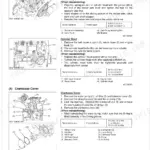
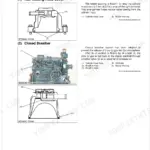
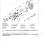
This is the Kubota workshop (service) manual for the B3000-AUS compact tractor, built around the Kubota V1505-E3-D21-Q diesel engine. It is the full repair reference, covering the engine, hydrostatic transmission, rear and front axles, brakes, steering, the hydraulic system, the electrical system, and the cab air conditioning, with servicing specifications and step-by-step disassembly and assembly procedures.
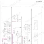
Across 428 pages you get tightening torques, clearance and wear limits, troubleshooting, wiring diagrams, and special-tool references, so an independent mechanic or a capable owner can diagnose a fault and rebuild an assembly correctly. This is the depth of information a dealer technician works from, not just an operator guide.
Delivered as a downloadable PDF you can open on any device and print the sections you need for the bench.
What's Inside This Manual
| System | Pages | Key Topics |
|---|---|---|
| General | Tractor Identification, Handling Precautions for Electrical Parts and Wiring (Battery, Fuse, Connector, Handling of Circuit Tester, Color of Wiring), Lubricants, Fuel and Coolant | |
| Engine | Servicing Specifications, Disassembling and Servicing (Checking and Adjusting, Preparation, Disassembling and Assembling) | |
| Transmission | Front Case, Hydrostatic Transmission (Structure, Pump and Motor, Oil Flow and Valves, Control Linkage), Cruise Control (Linkage), Range Gear Shift Section | |
| Rear Axle | Structure, Disassembling and Servicing (Disassembling and Assembling) | |
| Brakes | Feature, Operation, Servicing Specifications, Disassembling and Servicing (Checking and Adjusting, Disassembling and Assembling) | |
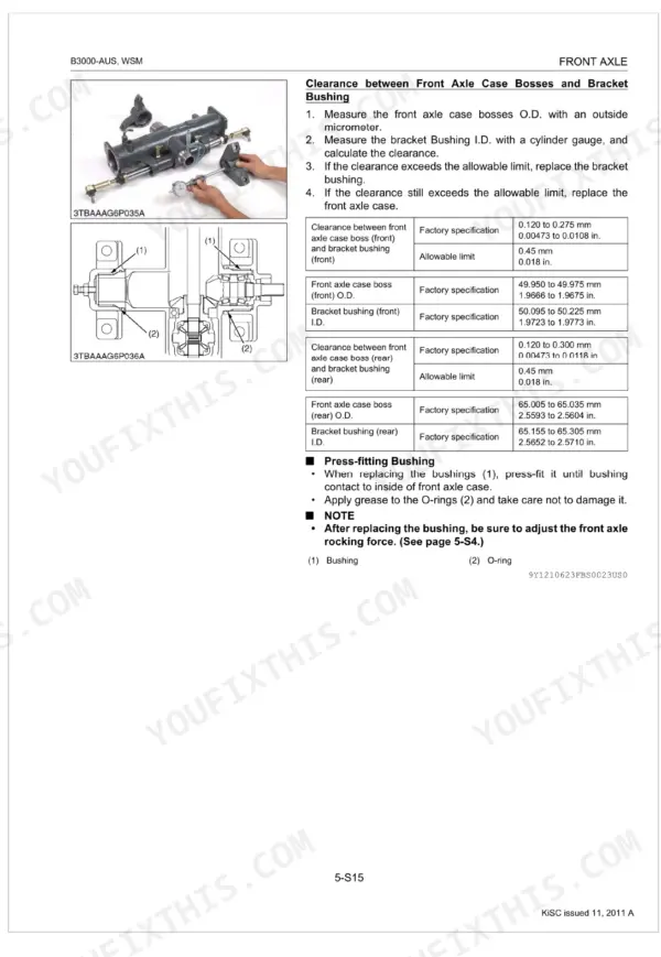
| Front Axle | Structure, Servicing Specifications, Disassembling and Servicing (Checking and Adjusting, Disassembling and Assembling) | |
| Steering | Steering Controller, Steering Cylinder, Hydraulic Circuit, Servicing Specifications, Disassembling and Servicing | |
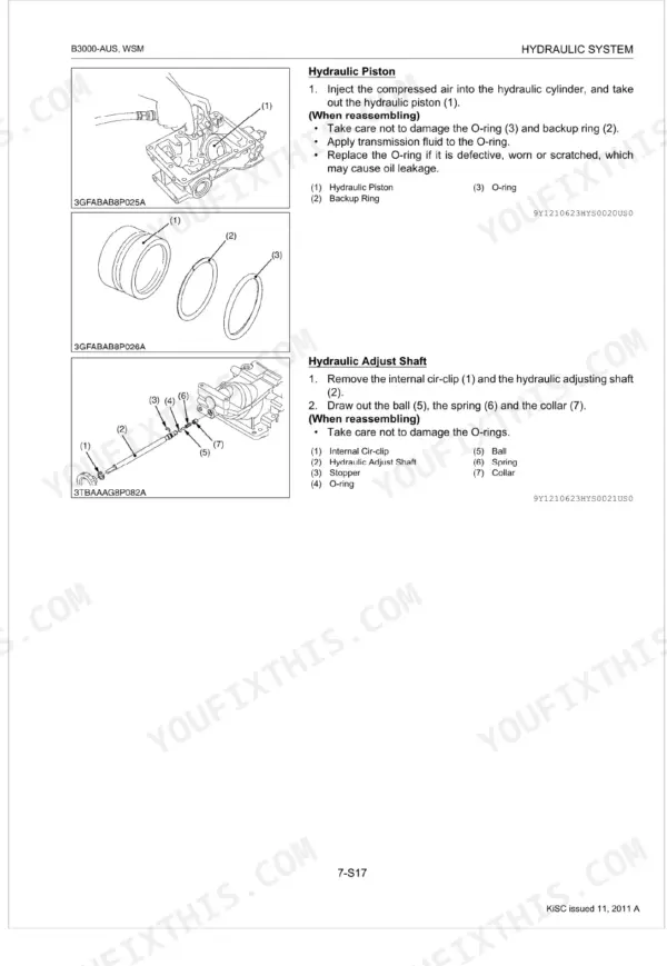
| Hydraulic System | Hydraulic Pump, Hydraulic Block, Power Steering (Hydraulic Circuit, Controller, Steering Cylinder) | |
| Electrical System | Wiring Diagram, Engine Starting System and Stopping System, Lighting System, Easy Checker, Servicing Specifications, Disassembling and Servicing | |
| Cabin | Outline of Air Conditioning System (Structure, Air Flow, Air Control Vent, Control Panel, Operation), Refrigeration System (Compressor, Condenser, Receiver, Air Conditioner Unit) |
Every system also includes checking, tightening torques, and troubleshooting.
Quick Reference Specifications
| Specification | Value | Page |
|---|---|---|
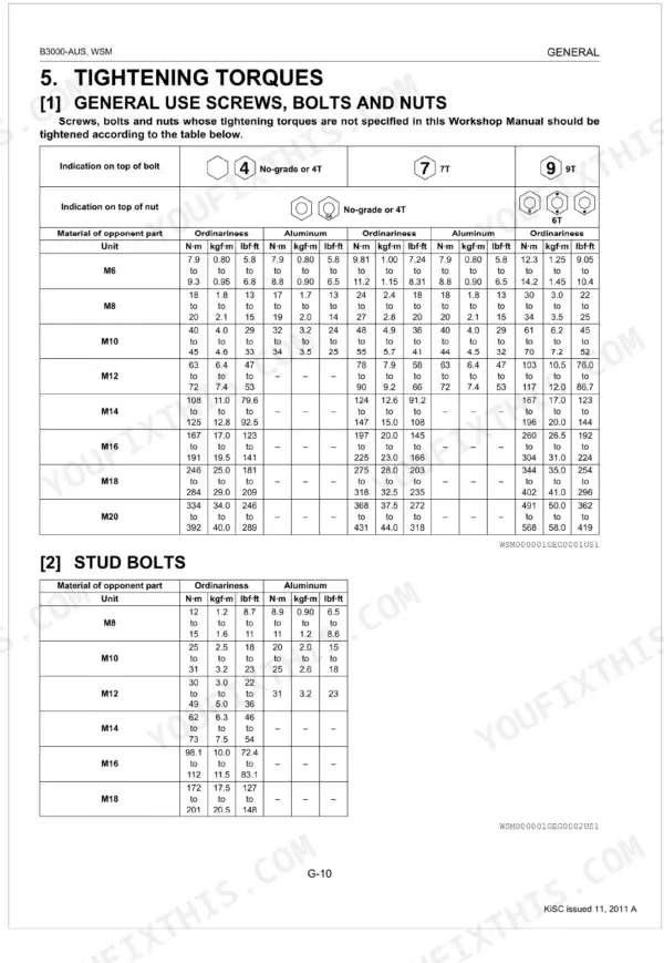
| General Use Screws, Bolts and Nuts (M6, Ordinariness) | 7.9 to 9.3 N·m | p. 26 |
| Transmission oil filter replacement interval | every 300 Hr | p. 29 |
| Fuel filter element replacement interval | every 400 Hr | p. 29 |
| Battery type | 55B24L (S)-MF | p. 40 |
| Battery capacity at 5H.R | 36 | p. 40 |
| Commutator O.D. (Factory specification) | 28.0 mm | p. 315 |
| Commutator O.D. (Allowable limit) | 27.0 mm | p. 315 |
| Main Switch Continuity (OFF position, B terminal - AC terminal) | Infinity | p. 39 |
| Main Switch Continuity (ON position, B terminal - AC terminal) | 0 Ω | p. 39 |
| Thermostat Valve Opening Temperature (At Beginning) | 69.5 to 72.5 °C | p. 88 |
| Thermostat Valve Opening Temperature (Opened Completely) | 85 °C | p. 88 |
| Fan Belt Tension (Factory specification) | 7.0 to 9.0 mm / 98 N | p. 88 |