

Part of the Kubota Repair Manuals.
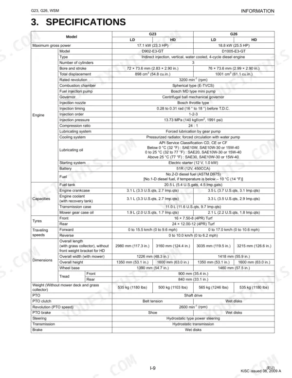
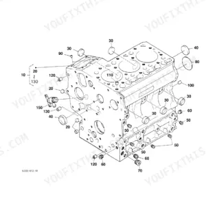
This is the Kubota G23 and G26 workshop manual, the factory service documentation for these front-mount diesel mowers and their D902-E3-GT and D1005-E3-GT engines. Across 343 pages it walks through the engine, transaxle and HST, front axle, steering, hydraulic system, electrical system, mower deck, and grass collector.
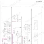
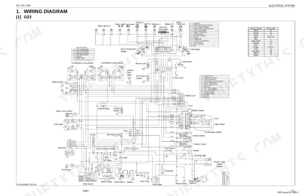
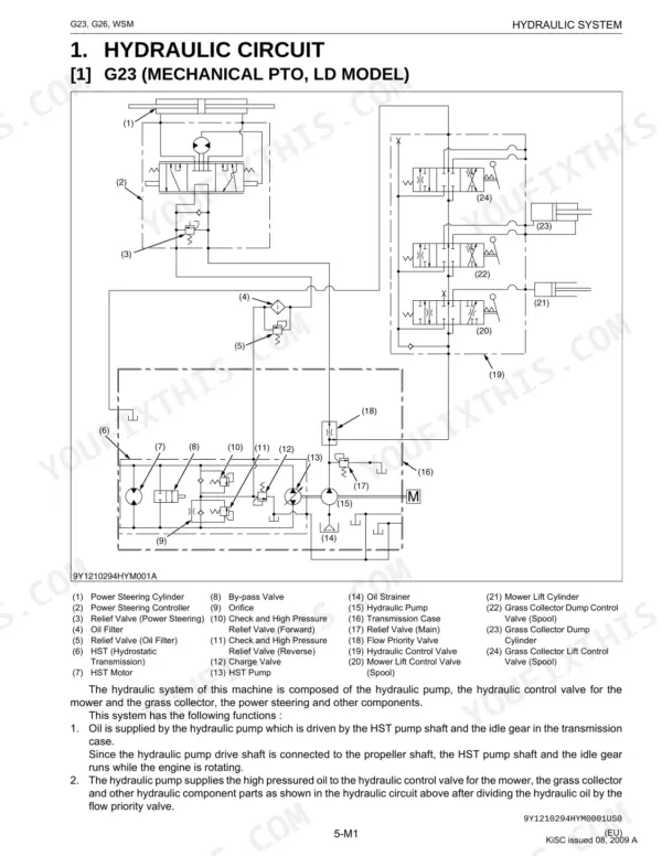
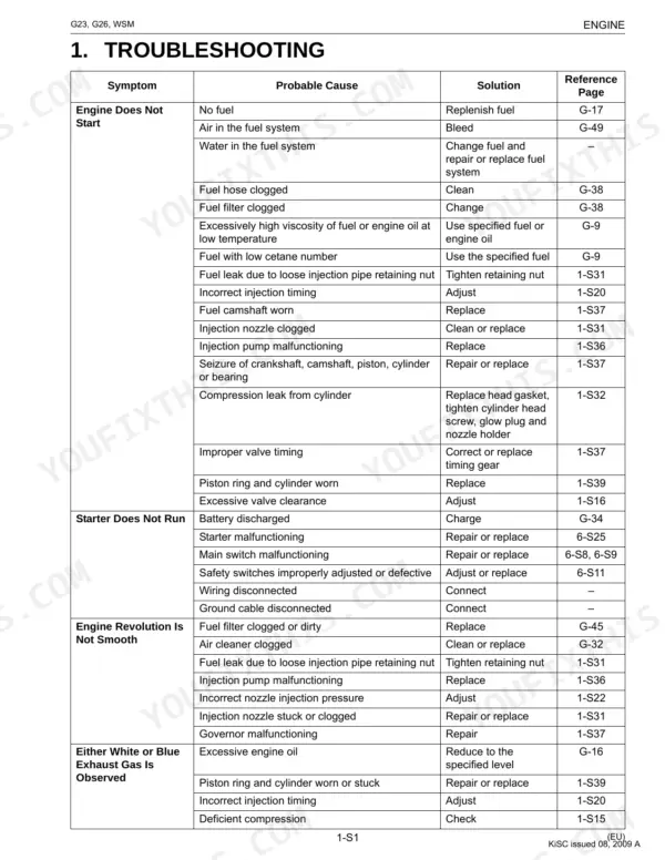
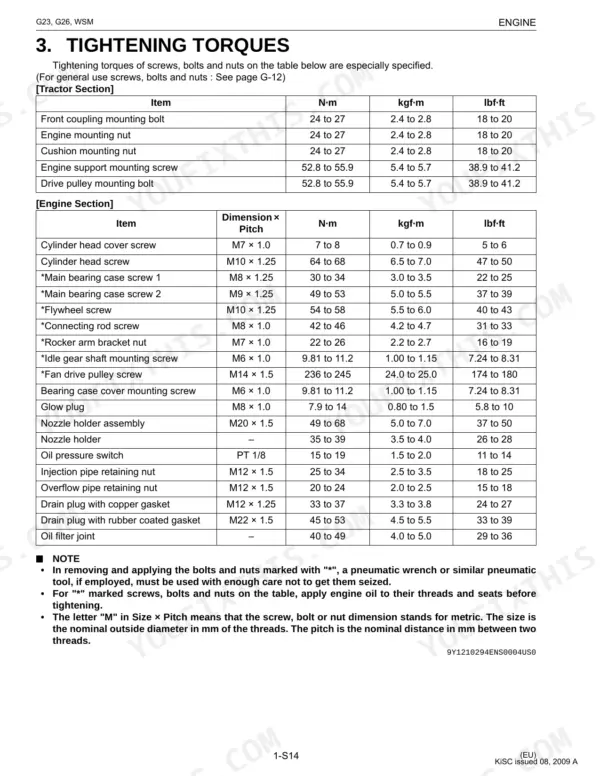
You get factory troubleshooting charts, servicing specifications, tightening torques, and step by step disassembly and reassembly for each system, along with wiring diagrams and hydraulic circuit drawings for both models. Whether you are chasing a no-start, rebuilding the HST, resealing a lift cylinder, or tracing a charging fault, the procedures and allowable limits are here.
Delivered as an instant PDF download you can read on any device or print, this is the same reference a Kubota technician uses to diagnose and repair the G23 and G26.
What's Inside This Manual
| System | Pages | Key Topics |
|---|---|---|
| To the Reader | Information, Safety First, Safety Label, Dimension, Engine Identification, Model Identification, General Precautions, Maintenance Check List | |
| G General | Tractor Identification, Serial Number, Cylinder Number, General Precautions, Wiring, Battery, Fuse, Connector | |
| Engine | G23, G26 | |
| Transaxle | HST Section, Rear Axle, Brake, PTO Clutch, Mechanical PTO Clutch, Hydraulic PTO Clutch | |
| Front Axle | Tie-Rod End, Center Pin, Pin Support Bushing, Bushing, Kingpin, Mower, Front Weight | |
| Steering | Hydraulic Circuit, G23 Mechanical PTO Clutch Model, G26 Hydraulic PTO Clutch Model, Steering Controller, Steering Cylinder | |
| Hydraulic System | Hydraulic Circuit, G23 (Mechanical PTO, Ld Model), Hd Model), G26 (Hydraulic PTO, Hydraulic Pump, Relief Valve, Flow Priority Valve | |
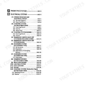
| Electrical System | Wiring Diagram, G23, G26, Starting System, Starting Circuit, Safety Switch, Charging System, Electrical Circuit | |
| Mower | Power Transmission, Mower Gear Case Power Train, Lifting Mechanism | |
| Grass Collector | Disassembling Grass Collector |
Quick Reference Specifications
| Specification | Value | Page |
|---|---|---|
| Cylinder head screw torque | 64 to 68 N·m (6.5 to 7.0 kgf·m, 47 to 50 lbf·ft) | p. 96 |
| Front coupling mounting bolt torque | 24 to 27 N·m (2.4 to 2.8 kgf·m, 18 to 20 lbf·ft) | p. 96 |
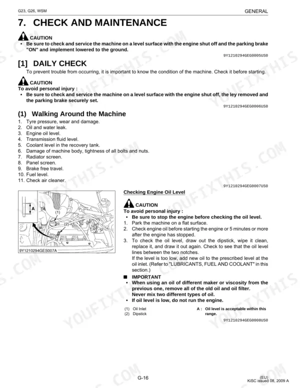
| Fuel filter element replacement interval | every 400 Hr | p. 32 |
| Battery terminal potential difference | Less than 0.1 V | p. 285 |
| Wiring harness sections | No specific numerical values for clearance, torque, or replacement are provided; only general instructions for inspection and repair/replacement if damaged or loose. | p. 22 |
| Fuse (1) capacity | 10 A | p. 68 |
| Slow blow fuse (9) capacity | 50 A | p. 68 |
| Fan belt deflection | 7.0 to 9.0 mm (0.28 to 0.35 in.) | p. 90 |
| Front PTO belt tension spring length | 88 to 91 mm (3.46 to 3.58 in.) | p. 54 |
| Transmission oil filter replacement interval | every 200 Hr | p. 32 |
| Main Relief Valve Setting Pressure | 12.3 to 12.8 MPa (125 to 131 kgf/cm2, 1790 to 1850 psi) | p. 251 |
| Radiator cap pressure falling time | More than 10 seconds for pressure fall 88 → 59 kPa (0.90 → 0.60 kgf/cm2, 13 → 8.6 psi) | p. 100 |