

Part of the Kubota Repair Manuals.
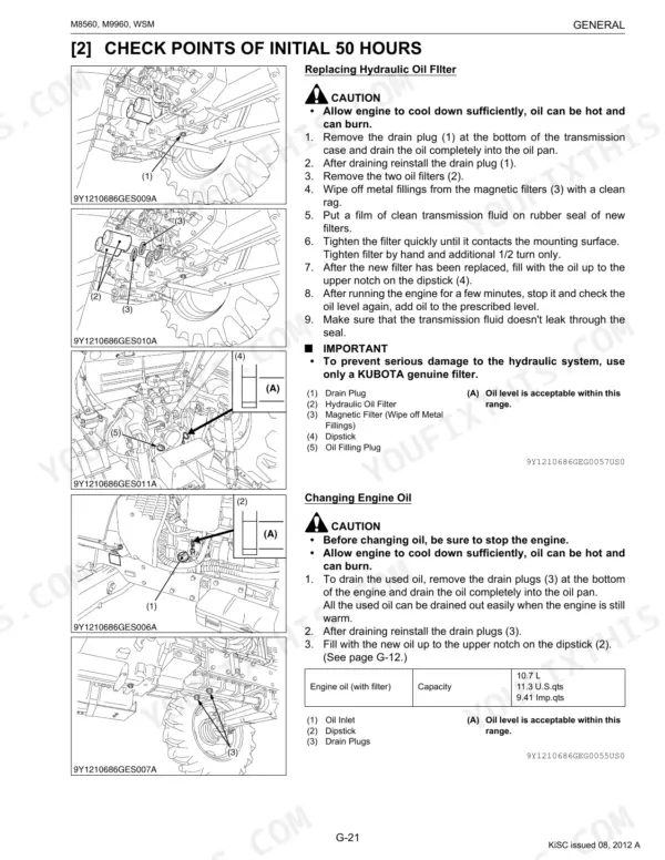
This Kubota Workshop Manual covers the M8560 and M9960 tractors, powered by Kubota's V3800-CR-TE4 and V3800-CR-TIE4 common rail diesel engines with after treatment. It runs 715 pages in English (publication 9Y111-06860) and gives structure, servicing specifications, tightening torques and step by step checking, disassembly and assembly procedures.
The content is grouped by system: engine, transmission, rear axle, brakes, front axle, steering, hydraulics, electrical and cabin, and it ends with full electric circuit diagrams. Owners and independent mechanics can diagnose faults, set valve clearance and brake free travel, rebuild major assemblies and confirm the torque, capacity and flow values for the ROPS and cabin builds. It downloads as a fully searchable PDF you can read on any device or print by section for bench work.
What's Inside This Manual
| System | Pages | Key Topics |
|---|---|---|
| I Information | 3-34 | |
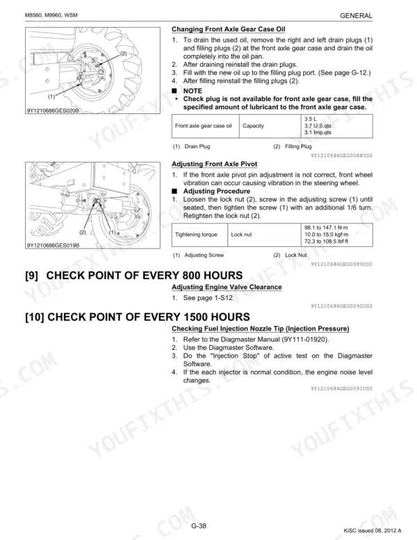
| G General | 35-135 | Tractor Identification, Handling Precautions for Electrical Parts and Wiring, Lubricant, Fuel and Coolant, Tightening Torques, Check and Maintenance, Special Tools |
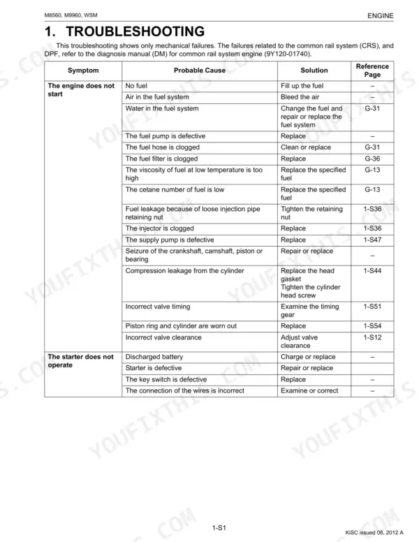
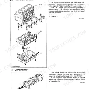
| Engine | 136-246 | Cylinder Block, Lubricating System, Cooling System, Common Rail System (Crs), EGR System, After Treatment System |
| Transmission | 247-396 | Structure, Power Train for Traveling Gear, Lubrication for Transmission, Power Train for PTO System, Power Train for 4WD, Differential Lock |
| Rear Axle | 397-417 | |
| Brakes | 418-445 | Traveling Brake, Master Cylinder Assembly, Parking Brake, Restriction Device |
| Front Axle | 446-478 | Structure, 2 Wheel Drive, 4 Wheel Drive, Limited Slip Differential (Lsd) |
| Steering | 479-498 | Steering Mechanism, Steering Cylinder |
| Hydraulic System | 499-550 | Hydraulic Circuit, Oil Cooler Relief Valve, Hydraulic Block, Position Control, Draft Control, Hydraulic Cylinder |
| Electrical System | 551-644 | Starting System, Instrument Panel, Lcd Monitor Indication, Eco 40 km/h Function, PTO Speed Limiter, Lighting System |
| Cabin | 645-713 | Air Conditioning System, Compressor, Air Conditioner Unit, System Control, Air Flow, Air Control Vent |
| Electric Circuit | 714-715 | Starting System and Charging System, Lighting System, Instrument Panel Board (Meter Panel), Main Control System (Tractor ECU), Engine Control System 1 (Engine ECU) |
Documents This Manual Refers To
The manufacturer cites these publications by number. We carry them:
Quick Reference Specifications
| Specification | Value | Page |
|---|---|---|
| All Models | ||
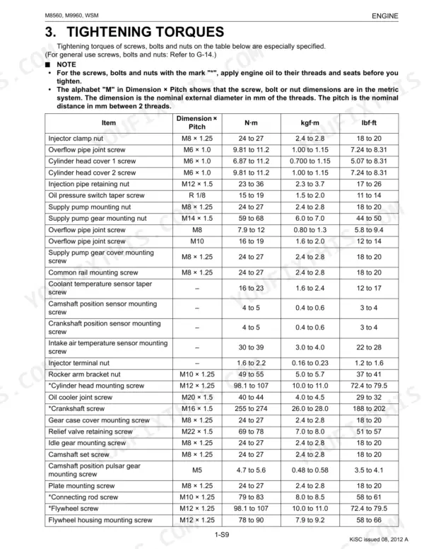
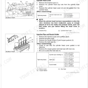
| Injector clamp nut torque | 24 to 27 N·m | p. 177 |
| Hydraulic Hose Fittings (Hose size 02) | 13.8 to 15.6 N·m | p. 52 |
| Engine start system check | Every 50 Hr | p. 54 |
| Battery condition check | Every 100 Hr | p. 54 |
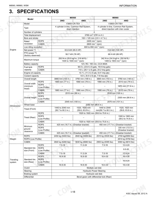
| Engine Oil Capacity (with filter) | 10.7 L | p. 49 |
| Coolant Capacity | 9.0 L | p. 49 |
| Engine Valve Clearance (Cold) | 0.23 to 0.27 mm | p. 172 |
| Connecting Rod Screw Torque | 79 to 83 N·m | p. 177 |
| ROPS | ||
| Fuel tank capacity, ROPS | 90.0 L | p. 49 |
| CABIN | ||
| Fuel tank capacity, CABIN | 110 L | p. 49 |
| ROPS Model | ||
| Fuel Tank Capacity (ROPS) | 90.0 L | p. 49 |
| CABIN Model | ||
| Fuel Tank Capacity (CABIN) | 110 L | p. 49 |