
Part of the New Holland Repair Manuals.
New Holland's REPAIR MANUAL for the D75, D85 and D95 crawler dozers, publication 87364107-NA dated 4/12/2007, printed by CNH America. It is one 1318-page PDF. It covers both the earlier and later serial series for each model, the N6DC and N7DC prefixes.
A dozer that sits with a slow blade or a stored fault code loses you working days. This book gives you the test numbers: 76.8 L/min pump output at 207 bar and 2000 RPM, 203 - 214 bar main relief, and oil at 52 - 79 C before any gauge goes on. Engine overhaul is in a separate Engine Repair Manual, which is not included here.
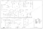
The chapters are lettered by system, from A Distribution Systems through J Tools and Couplers. The electrical and hydraulic schematics are grouped at the back, so you can go straight to the chapter that matches the fault.
What's Inside This New Holland D75, D85, D95 Repair Manual
| System | Pages | Key Topics |
|---|---|---|
| Contents and Introduction | 2-18 | Contents, Safety, Serial Ranges for the Earlier and Later Series of Each Model |
| Distribution Systems (a) | 19-506 | Primary and Secondary Hydraulic Power System, Relief Valve Pressure Test, Pump Flow Test, Stack Valve, Electrical Power System, Lighting, Fault Codes |
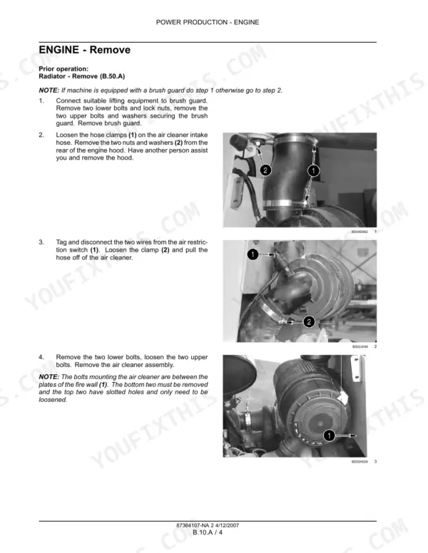
| Power Production (B) | 507-612 | Engine Mounting Torques and Speeds, Fuel and Injection, Air Intake, Engine Coolant, Lubrication, Starting System |
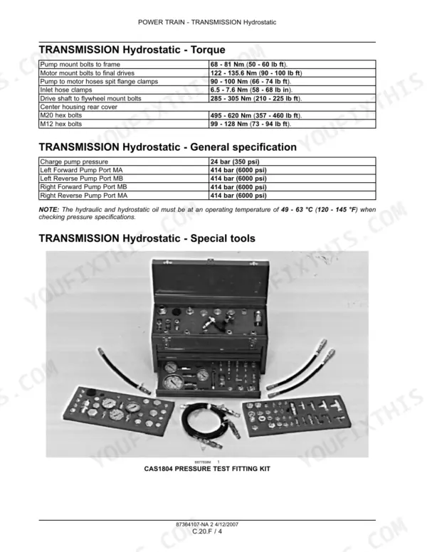
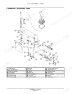
| Power Train (C) | 613-682 | Fixed Coupling, Hydrostatic Transmission, Command Display and Service Switch |
| Travelling (D) | 683-930 | Hydraulic Service Brake and Parking Brake, Tracks, Rollers, Final Drive |
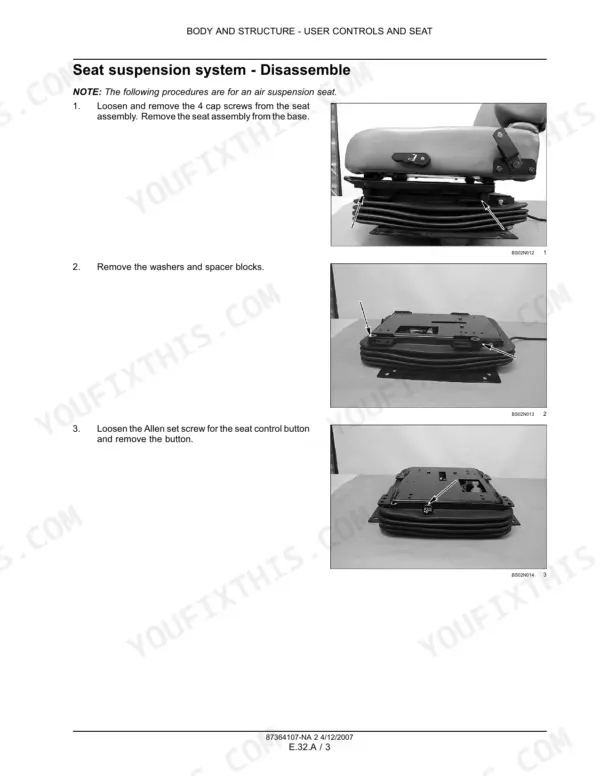
| Body and Structure (E) | 931-1158 | User Controls and Seat, Instrument Cluster, User Platform, Heating and Air-Conditioning, Safety |
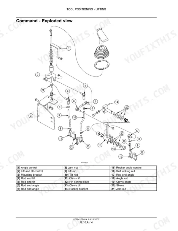
| Tool Positioning (G) | 1159-1272 | Lifting, Tilting and Swinging Cylinders |
| Working Arm (H) | 1273-1282 | Single Arm Tool Attachment |
| Tools and Couplers (J) | 1283-1314 | Digging Tools, Dozer Blade |
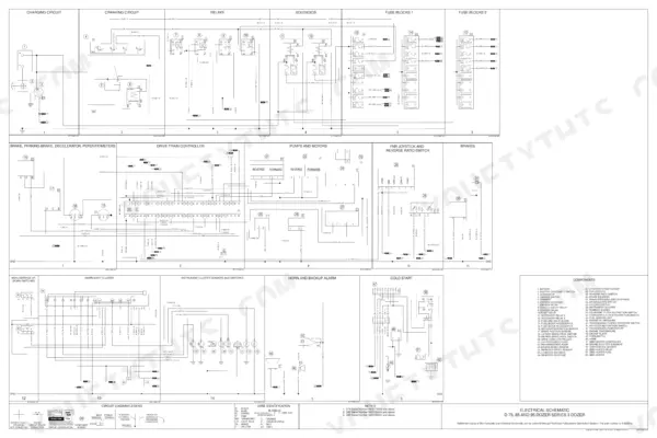
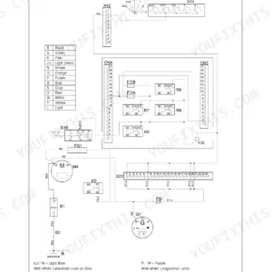
| Schematics | 1315-1318 | Electrical Schematics Series 2 and Series 3, Hydraulic Schematic |
Quick Reference Specifications
| Specification | Value | Page |
|---|---|---|
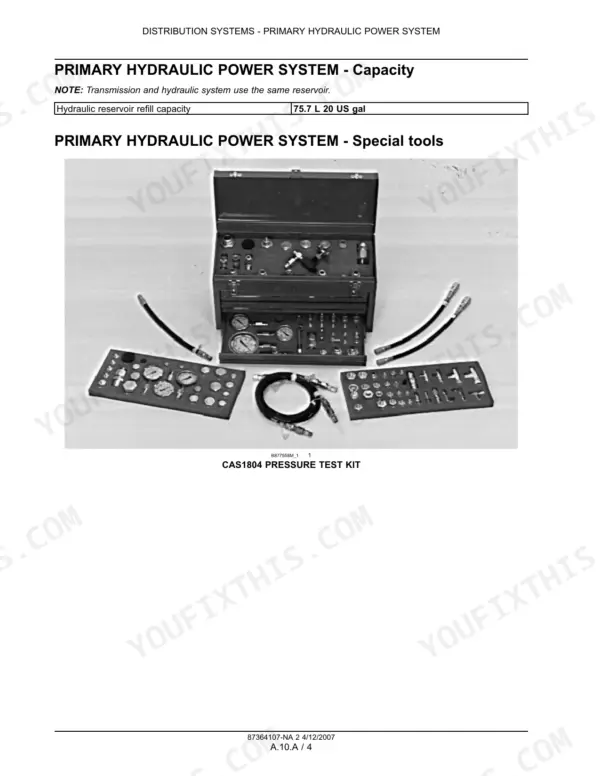
| Hydraulic reservoir refill capacity | 75.7 L (20 US gal) | p. 24 |
| Hydraulic oil temperature when testing | 52 - 79 C (125 - 175 F) | p. 27 |
| Hydraulic pump output | 76.8 L at 207 bar at 2000 RPM (20.3 US gpm at 3000 psi) | p. 27 |
| Neutral system pressure | 12 - 15 bar (180 - 220 psi) at 2000 RPM | p. 27 |
| Main relief valve pressure | 203 - 214 bar (2950 - 3100 psi) at 2000 RPM | p. 27 |
| Circuit relief valves | 214 - 227 bar (3100 - 3300 psi) | p. 27 |
| Engine low idle | 800 to 1050 rpm | p. 511 |
| Engine high idle no load | 2170 to 2270 rpm | p. 511 |
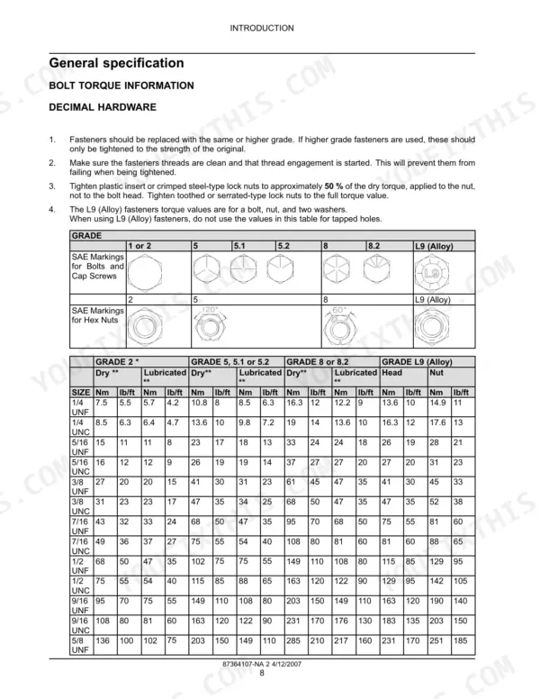
| Engine mount bolts to chassis | 205 - 230 Nm (151 - 170 lb ft) | p. 511 |
| Rear engine mount brackets to bell housing | 118 - 133 Nm (87 - 98 lb ft) | p. 511 |
| Lower roller mounting bolts | 217 - 244 Nm (160 - 180 lb ft) (D75) / 386 - 434 Nm (285 - 320 lb ft) (D85, D95) | p. 733 |
| Final drive drain plug | 43 - 46 Nm (32 - 34 lb ft) | p. 700 |
New Holland D75, D85, D95 Common Problems This Manual Covers
Blade lifts slowly or the machine has no hydraulic power
Warm the oil to 52 - 79 C and check the main relief first. Gauge on the test port coupler, full throttle, lift lever held in RAISE, and look for 203 - 214 bar. If relief is in spec, run the flowmeter test. Compare flow at 138 bar with flow at minimum pressure to judge pump wear.
Manual Section: A Distribution Systems - Primary hydraulic power system (relief valve pressure test, pump flow test) p. 44Fault code stored and the engine stalls under heavy load
An out-of-range throttle potentiometer circuit turns off anti-stall, so the engine lugs down and dies. Read the codes on the Command Display with the service/enter switch. Record codes, hours and occurrences before clearing. Then check the connectors, look for water in them and trace the wiring.
Manual Section: A Distribution Systems - Fault codes p. 411Machine moves during the service brake preliminary test
If the dozer creeps at 950 rpm in F or R with the parking brake levers released, the brakes were misassembled. Go back through the brake assembly steps. After the test, check the final drive drain for fluid and reinstall the plug at 43 - 46 Nm.
Manual Section: D Travelling - Hydraulic service brake and parking brake p. 700A gauge works only part of the time
Start at the cheap end. Check the connection at the sender, then at the instrument cluster, then at each harness connector in between. Then check the wires between the cluster and the sender for a short or open circuit. Only then condemn the sender or the gauge.
Manual Section: A Distribution Systems - Electrical power system; Schematics - Series 2 and Series 3 electrical p. 960Frequently Asked Questions
How do I check whether the main relief valve is set low?
Bring the oil up to 52 - 79 C (125 - 175 F) first. Put a gauge on the test port coupler, run the engine at full throttle and hold the lift lever in RAISE. The spec is 203 - 214 bar (2950 - 3100 psi) at 2000 RPM. The procedure is in Distribution Systems under the primary hydraulic power system. p. 44
How do I tell if the equipment pump is worn?
Run the flowmeter test in Distribution Systems. The book judges wear by comparing flow at 138 bar with flow at minimum pressure. A good pump puts out 76.8 L/min at 207 bar at 2000 RPM. That one test pays for itself before you pull a pump that turns out to be fine. p. 30
How do I read the fault codes on the Command Display?
Use the service/enter switch to bring up the codes stored by the drivetrain control module. Before you clear anything, write down each code with its hours and number of occurrences. For a code such as 4321, throttle potentiometer circuit out of range, the fault code section then has you check the connectors, water in the connectors and the wiring. p. 626
How is the service brake preliminary test run?
Release the parking brake levers, select F or R and run the engine at 950 rpm for 1 minute. If the machine moves, the brakes are misassembled. After the test, check for fluid at the final drive drain. The drain plug goes back in at 43 - 46 Nm (32 - 34 lb ft). p. 700
Do the lower roller bolt torques differ between models?
Yes. On the D75 the lower roller mounting bolts take 217 - 244 Nm (160 - 180 lb ft). On the D85 and D95 they take 386 - 434 Nm (285 - 320 lb ft). Don't carry one number across a mixed fleet. Both values are in Travelling, with the tracks, rollers and idlers. p. 733






Reviews
There are no reviews yet.