
Part of the New Holland Repair Manuals.
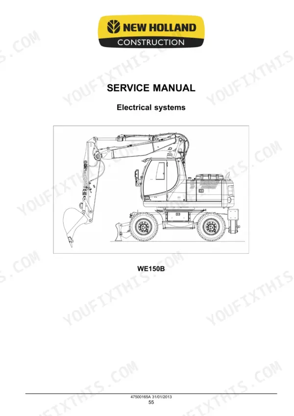
New Holland service manual 47500165A covers the WE150B in both 2-piece boom (triple articulate) and monoboom form. It runs from the powershift transmission and axles through swing, travel, the pilot circuit, the main control valve, the cylinders and the cab A/C. It includes three hydraulic schematic frames and 33 electrical frames.
The engine overhaul is in a separate Engine Service Manual. Diagnostic code troubleshooting in the Electrical Systems section gives a cause and a remedy for each code, for example code 7002, low pressure on brake valve, which points to the accumulator charge.
What's Inside This New Holland WE150B Manual
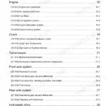
| System | Pages | Key Topics |
|---|---|---|
| Introduction and General Specifications | 1-49 | Safety Rules, Product Overview, Dimensions, Weights, General Specifications, Consumables, Product Identification |
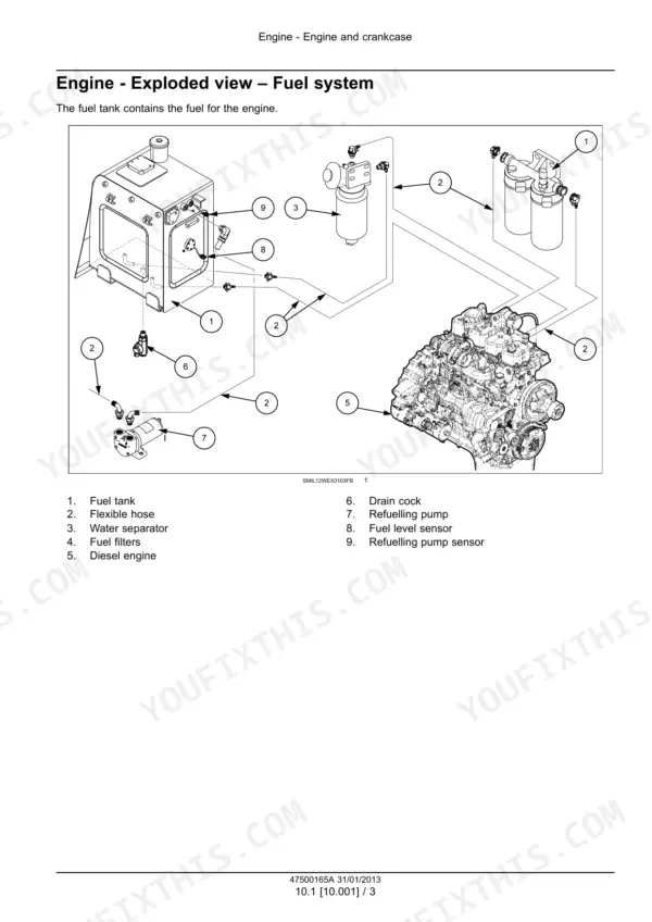
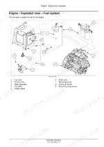
| Engine | 50-109 | Fuel System, Air Cleaners, Fuel Filters, Fuel Tank, Exhaust Manifold and Muffler, Radiator, Thermal Bypass Valve, Expansion Tank |
| Transmission | 110-175 | Transmission Lubrication, Powershift Transmission, External Controls, Clutch Packs, Internal Components, Disassembly and Assembly |
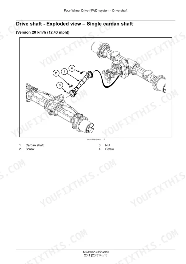
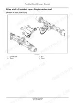
| Four-Wheel Drive System and Axles | 176-309 | Drive Shaft, Front Steering Axle, Rear Rigid Axle, Bevel Gears, Differentials, Final Drives, Steering Knuckles, Floating Axle Locking |
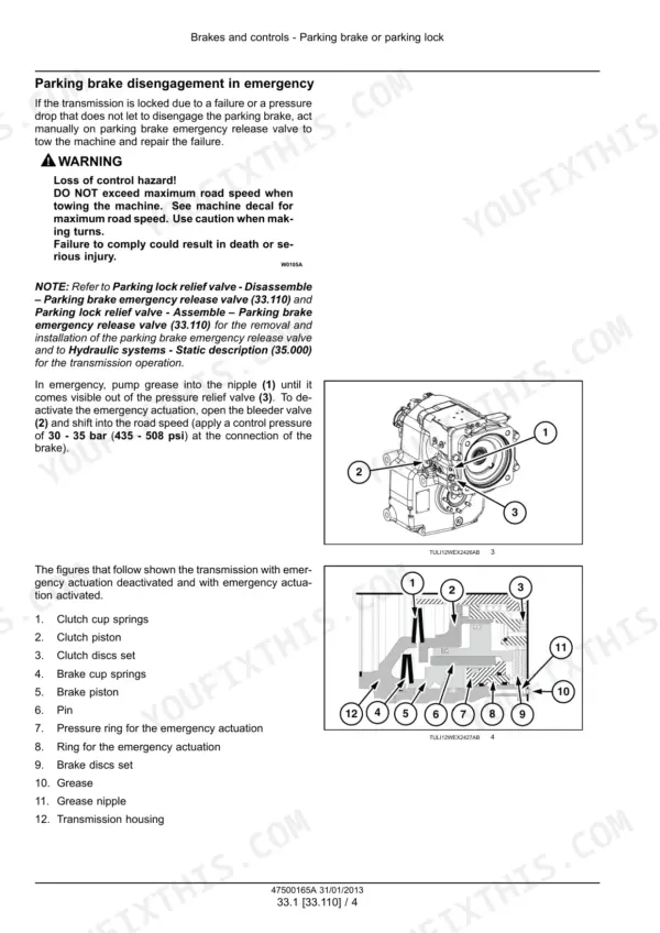
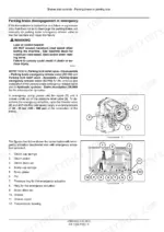
| Brakes and Controls | 310-345 | Parking Brake, Hydraulic Service Brakes, Brake Pedal Valve, Accumulators, Brake Pressure Warning, Functional Diagram |
| Hydraulic Systems | 346-451 | Hydraulic Schematics, Valve Specifications, Calibration Requirements, Pump Control Valves, Variable Displacement Pump, Reservoir and Filters, Double Gear Pump |
| Hydraulic Swing System and Travel | 452-551 | Slewing Gearbox, Swing Pump, Swing Calibration, Travel Motor, Motor Displacement Control, Hydraulic Central Joint |
| Pilot System and Main Control Valve | 552-625 | Pilot Pressure Control, Proportional Valves, Main Control Valve, Valve Calibration, Hydraulic Hammer, Rotating Bucket, Shear Control |
| Stabilizer, Boom, Dipper and Blade Cylinders | 626-727 | Stabilizer Cylinders, Positioning Cylinder, Boom Cylinders, Hose Break Protection Valves, Dipper Cylinder, Bucket Cylinder, Dozer Blade Cylinders |
| Frames, Steering and Wheels | 728-809 | Swing Ring Assembly, Stabilizers, Counterweight, Steering Control, Tie Rods, Power Steering, Steering Cylinders, Tyre Replacement and Pressure Checks |
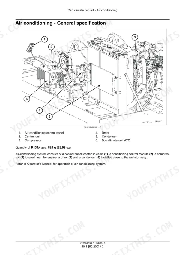
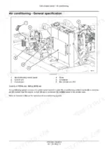
| Cab Climate Control | 810-823 | Air Conditioning Specifications, Refrigerant Charge, Compressor Removal and Installation, Condenser Removal and Installation, Dryer |
| Electrical Systems and Diagnostic Codes | 824-873 | Diagnostic Display Indications, Diagnostic Code Lists, Mechanical and Electrical Fault Causes, Sensor and Solenoid Faults, Troubleshooting Remedies |
| Fuel Injection and Sensors | 874-923 | Fuel Injection Control, Coolant Temperature Sensor, Engine Intake System, VDO Engine Speed Control, Transmission Speed Sensor, Parking Brake Sensor, Hydraulic Oil Temperature Sensor, HVAC Control |
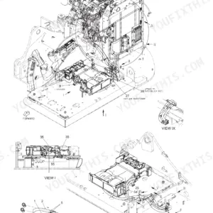
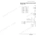
| Harnesses, Connectors and Electrical Schematics | 924-1043 | Fuses, Power Supply Schematics, Sensor Wiring, Lighting Circuits, Gear and Brake Circuits, UCM Electrovalves, CAN Bus and EST, Harness Localisation |
| Rotary Joint, Battery, Lighting and Control Modules | 1044-1117 | Electrical Rotary Joint, Battery, External and Cab Lighting, Rotation Speed Sensor, CAN Bus Controls, Accelerator Potentiometer, Rear View Camera, UCM Modules |
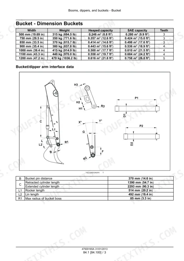
| Booms, Dippers and Buckets | 1118-1135 | Bucket Dimensions, Bucket Pins, Bucket Removal and Installation, Corrosion Protection, Bucket Teeth, 2-Piece Boom Attachment, Monoboom Attachment |
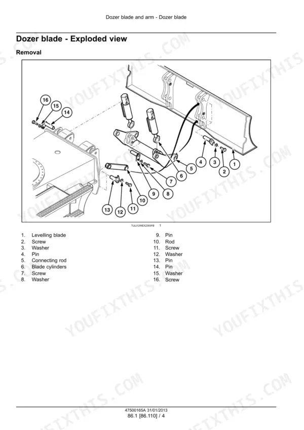
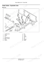
| Dozer Blade and Arm | 1136-1145 | Blade Specifications, Exploded View, Static Description, Blade Removal |
| Platform, Cab, Bodywork and Special Tools | 1146-1175 | Ladder Description, Ladder Removal and Installation, Operator Seat, Cabin Structure, Cab Removal and Installation, Special Tool Index |
Quick Reference Specifications
| Specification | Value | Page |
|---|---|---|
| Engine type | F4GE9484D*J601 | p. 46 |
| Engine displacement | 4.5 l (1.2 US gal) | p. 46 |
| Engine power | 90 kW (122.4 Hp) at 2000 RPM | p. 46 |
| Engine maximum torque | 525 N·m (387.2 lb ft) at 1200 RPM | p. 46 |
| Engine rated rpm | 2000 RPM ± 50 | p. 46 |
| Fuel tank capacity | 190 l (50.2 US gal) | p. 46 |
| Hydraulic system total volume | ~ 210 l (55.5 US gal) | p. 47 |
| Weight, triple articulate, 2100 mm dipper, front blade and rear stabilizers | 16300 kg (35935.3 lb) | p. 33 |
| Weight, monoboom, 2100 mm dipper, front blade and rear stabilizers | 16000 kg (35274.0 lb) | p. 33 |
| Attachment circuit pressure (2-piece boom) | 340 bar (4930.0 psi) | p. 42 |
| Travel circuit pressure | 370 bar (5365 psi) | p. 42 |
| Power boost pressure | 370 bar (5365 psi) | p. 42 |
| Pilot system pressure | 45 bar (653 psi) | p. 42 |
| Service brake valve setting | 75 bar (1088 psi) | p. 352 |
| Transmission operating pressure | 32 bar (464 psi) | p. 352 |
| Maximum travel speed on the road | 20 km/h (12.4 mph) | p. 44 |
| High speed on road (optional) | 35 km/h (21.7 mph) | p. 44 |
| Tyre pressure, twin Mitas 10.00-20 PR16 NB38 | 7.5 bar (109 psi) | p. 44 |
| Rear axle mounting screw torque | 670 N·m (494 lb ft) | p. 271 |
| Wheel nut tightening torque | 450 - 550 N·m (332 - 406 lb ft) | p. 805 |
New Holland WE150B Common Problems This Manual Covers
Code 9618: open circuit on pump P1 pressure sensor B211
The diagnostic code tables put this on the pump P1 pressure sensor B211, with damaged wiring 37C as the cause and replacing the wiring 37C as the fix. The diagnostic code tables list the electrical and mechanical causes for each code, and the harness schematic frames in Harnesses and Connectors show where circuit 37C runs.
Manual Section: Electrical systems - Troubleshooting related to diagnostic code 9618 p. 845Code 7002: low pressure on brake valve
The code list points to an unsatisfactory accumulator charge, so check the accumulators first. The Brakes and Controls section covers the brake pedal valve, the accumulators and the brake pressure warning. It also gives the 75 bar (1088 psi) service brake valve setting to confirm the circuit against.
Manual Section: Electrical systems - Troubleshooting related to diagnostic code 7002 p. 837Code 7001: low pressure on power steering
The fault table names a damaged priority valve as the cause. Measure the pressure difference between port P and port CF of the priority valve. If it is more than 1 bar, replace the priority valve. The steering control, power steering and steering cylinders are covered under Frames, Steering and Wheels.
Manual Section: Electrical systems - Troubleshooting related to diagnostic code 7001 p. 836Code 7021: battery charge control of alternator G1 damaged with engine On
The diagnostic code table for 7021 lists a mechanical cause, alternator damaged, and the remedy is to replace the alternator. The same table also has an electrical branch with its own wiring check, and the Rotary Joint, Battery, Lighting and Control Modules section covers the battery.
Manual Section: Electrical systems - Troubleshooting related to diagnostic code 7021 p. 840Frequently Asked Questions
Which machines and versions does this New Holland WE150B service manual cover?
It covers the WE150B wheeled excavator in both the 2-piece boom (triple articulate) and monoboom versions. The part number is 47500165A, in English, published January 2013 by New Holland Construction. No serial ranges are printed, so match it by model and boom type. p. 1
What engine and power rating does the WE150B use?
The engine type is F4GE9484D*J601, a water-cooled turbocharged diesel of 4.5 l (1.2 US gal). It makes 90 kW (122.4 Hp) at 2000 RPM and 525 N·m (387.2 lb ft) at 1200 RPM. Rated speed is 2000 RPM ± 50. This book covers the fuel system, filters, radiator and thermal bypass valve. Internal overhaul is in the separate Engine Service Manual. p. 46
What hydraulic working pressures does the WE150B manual give?
Attachment circuit pressure on the 2-piece boom is 340 bar (4930.0 psi). Travel and power boost are both 370 bar (5365 psi). Pilot system pressure is 45 bar (653 psi). The service brake valve is set at 75 bar (1088 psi), and transmission operating pressure is 32 bar (464 psi). p. 42
What are the fuel tank and hydraulic system capacities of the New Holland WE150B?
The fuel tank holds 190 l (50.2 US gal). Total hydraulic system volume is about 210 l (55.5 US gal). That figure is the whole system, not just the reservoir. p. 46
Does the New Holland WE150B manual include wiring diagrams, hydraulic schematics and diagnostic codes?
Yes. Hydraulic schematic frames 01 to 03 are included, and frame 03 is the undercarriage hydraulic diagram. Electrical frames 01 to 33 run from power supply through to CAN bus. The Electrical Systems section lists codes such as 7000 and 9618, each with its cause and remedy. Code 7001, for example, has you check the pressure difference between port P and port CF on the priority valve. p. 929





Reviews
There are no reviews yet.