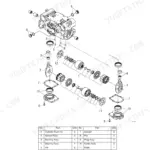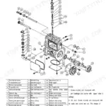
Part of the Yanmar Repair Manuals.
Drop a dial indicator on the crank nose of a stripped TNE block and you need one number: how much endplay is too much. That is the kind of figure this Yanmar factory service manual exists to settle, for the whole TNE family: 2TNE68, 3TNE68, 3TNE74, 3TNE78A, 3TNE82A, 3TNE82, 3TNE84, 3TNE88, 4TNE82, 4TNE84 and 4TNE88, plus the turbocharged 3TNE84T and 4TNE84T.
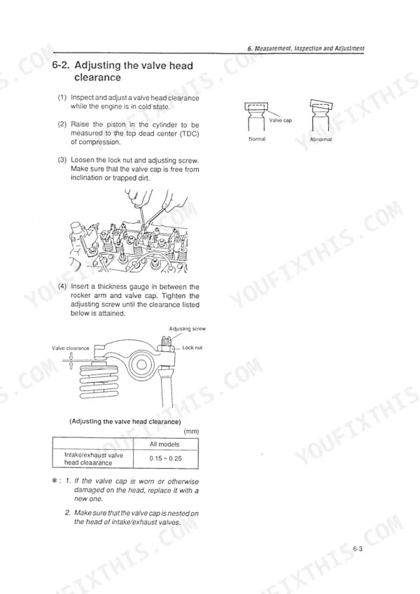
Whether the engine sits on a stand or is still bolted where it works, the manual takes you from diagnosis to reassembly: compression testing, valve lash, injector pop pressure and spray pattern checks, injection timing, then full measuring procedures with service limits for the head, block, pistons, rods, camshaft and crankshaft. Separate chapters rebuild the injection pumps (indirect and direct), the governor and the turbocharger.
It is a 134 page English PDF, sized to print the pages you need and take them to the bench.
Complete the set for your TNE Series
- Parts Catalog: Yanmar 3TNE68, Y00V3629 Engine Parts Catalog
- Parts Catalog: Yanmar 4TNE88 Small Vertical Engine Parts Catalog
- Parts Catalog: Yanmar 4TNE88 Parts Catalog
What's Inside This Manual
| System | Pages | Key Topics |
|---|---|---|
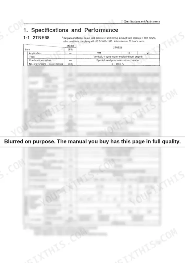
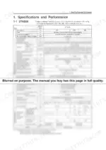
| Specifications and Performance | 6-18 | 2TNE68, 3TNE68, 3TNE74, 3TNE78A, 3TNE82A, 3TNE82, 3TNE84, 3TNE88 |
| Cross Sectional Views | 19-21 | Special Swirl Pre-Combustion Chamber System, Direct Injection System |
| Cooling Water, Lubricating Oil and Fuel Oil | 22-24 | Cooling Water, Lubricating Oil, Fuel Oil |
| Troubleshooting | 25-27 | Trouble Causes and Remedies, Trouble Diagnosis Through Measurement of Compression Pressure |
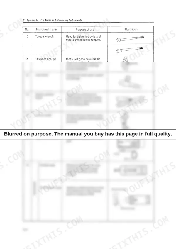
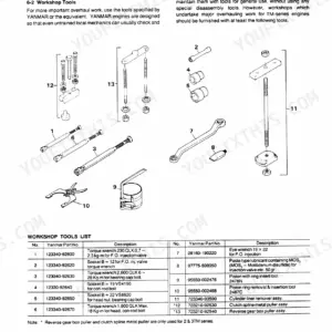
| Special Service Tools and Measuring Instruments | 28-34 | Special Service Tools, Measuring Instruments |
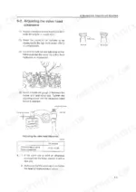
| Measurement, Inspection and Adjustment | 35-49 | Measuring the Compression Pressure, Valve Head Clearance, Checking the V-Belt Tension, Measuring and Checking the Injection Pressure and Spray Patterns of the Fuel Injection Valve |
| Measuring Procedures, Service Data and Corrective Action | 50-76 | Cylinder Head, Cylinder Block, Valve Rocker Arm, Piston and Piston Ring, Connecting Rod, Camshaft, Crankshaft, Gears |
| Disassembly and Reassembly | 77-84 | Disassembly, Precautions Before and During Reassembly |
| Service Data | 85-94 | Cylinder Head, Cylinder Block, Valve Rocker Arm, Piston, Piston Ring, Connecting Rod, Camshaft, Crankshaft |
| Fuel Injection Pump for Indirect Injection System | 97-101 | Fuel Injection Pump, Bottom Cover, Fuel Feed Pump, Governor Weight Assembly, Governor Weight Extractor Tool, Fuel Injection Pump Side Cover, Plunger Guide, Tappet Holders |
| Fuel Injection Pump for Direct Injection System | 102-114 | Fuel Injection Pump, Plunger Guide, Plunger Barrel, Fuel Injection Pump Camshaft, Bearing, Control Rack, Fuel Control Pinion, Governor |
| Governor | 115-128 | Governor Lever Shaft Assembly, Torque Spring Assembly, Springs, Angleich Spring Assembly, Governor Weight Assembly, Stop Lever, Control Lever Shaft, Governor Link |
| Turbocharger | 129-134 | Specifications, Waste Gate Valve Adjusting Method, Exploded View of Turbocharger, Tightening Torque, Service Standards |
Quick Reference Specifications
| Specification | Value | Page |
|---|---|---|
| V-belt tension (deflection) | 10-15 mm | p. 37 |
| Intake/exhaust valve head clearance | 0.15 ~ 0.25 mm | p. 37 |