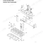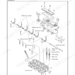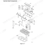



Part of the Yanmar Repair Manuals.
When the swing motor drags every cold morning until the oil warms up, the crew stands around while you guess at pilot pressure, brake valve, or motor wear. This Yanmar SV100 service manual ends the guessing: 546 pages of factory procedures for the SV100 excavator and its 4TNV98T-SBV turbocharged diesel, delivered as an English PDF you download immediately.
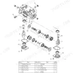
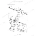
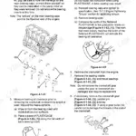
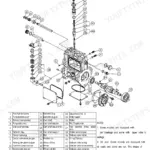
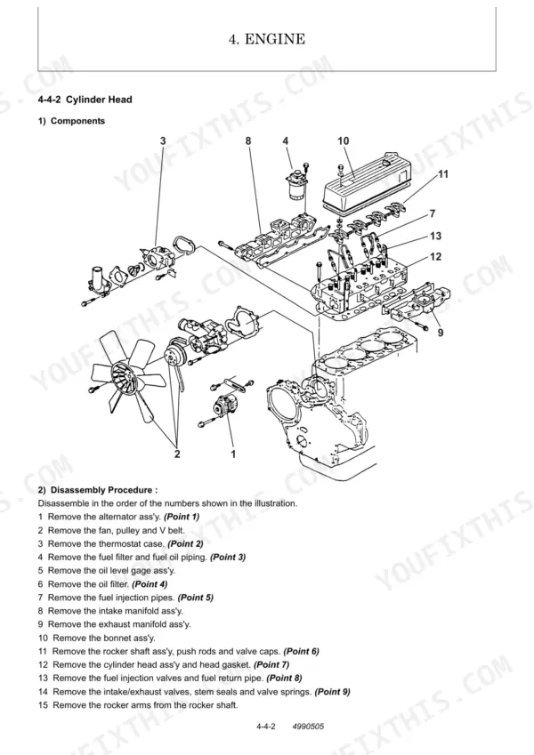
Inside are full teardown and reassembly steps for the engine, fuel injection pump, turbocharger, starter, and alternator, plus hydraulic circuit operation for boom, arm, bucket, swing, blade, and travel. The swing motor, travel motor, pump, and control valve each get their own disassembly and troubleshooting coverage, and undercarriage service covers both rubber and steel crawlers.
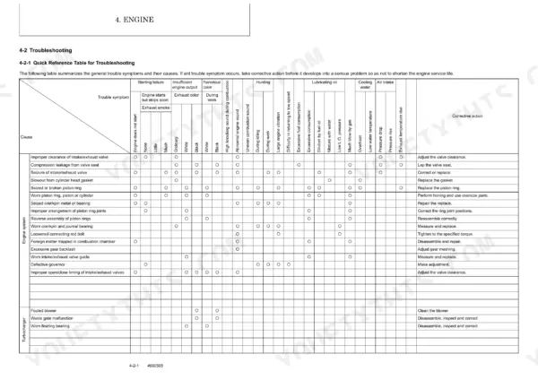
Service standards, torque lists, and relief pressure settings sit in their own sections, so you can go from a symptom in the troubleshooting tables straight to the page that fixes it.
Complete the set for your SV100
- Parts Catalog: Yanmar SV100 Parts Catalog (Excavator)
What's Inside This Manual
| System | Pages | Key Topics |
|---|---|---|
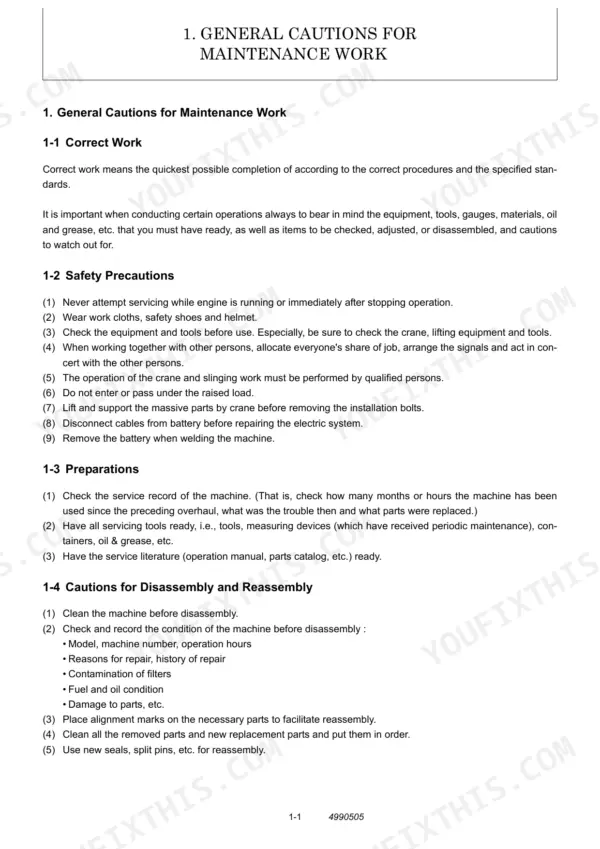
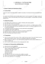
| General Cautions for Maintenance Work | 11-24 | Correct Work, Safety Precautions, Preparations, Cautions for Disassembly and Reassembly, Hydraulic Equipment Removal and Installation, Hydraulic Hose Installation and Specifications, Air Release of Hydraulic Equipment |
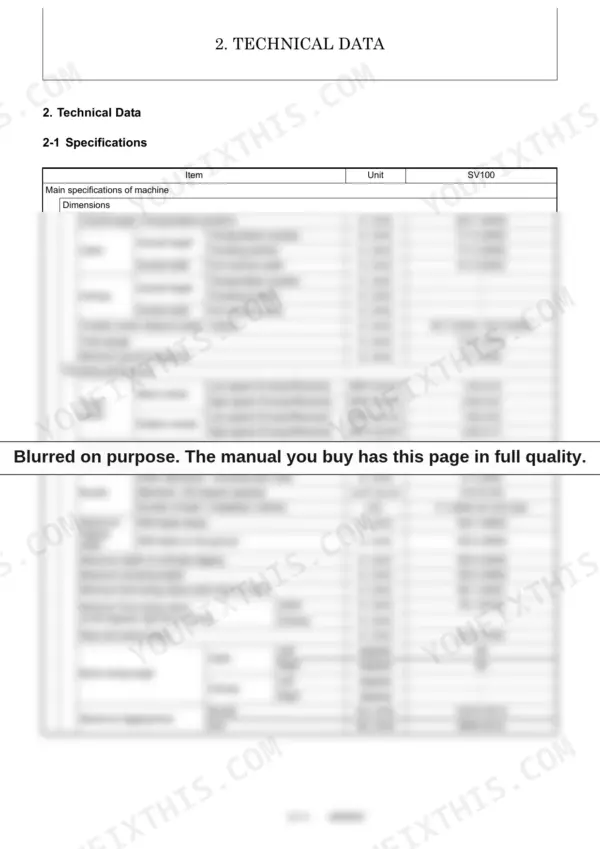
| Technical Data | 25-38 | Machine Specifications, Outline Drawing and Working Area (Quick Coupler, W/O Quick Coupler), Weight List of Main Parts, Lifting Capacity List (SV100) |
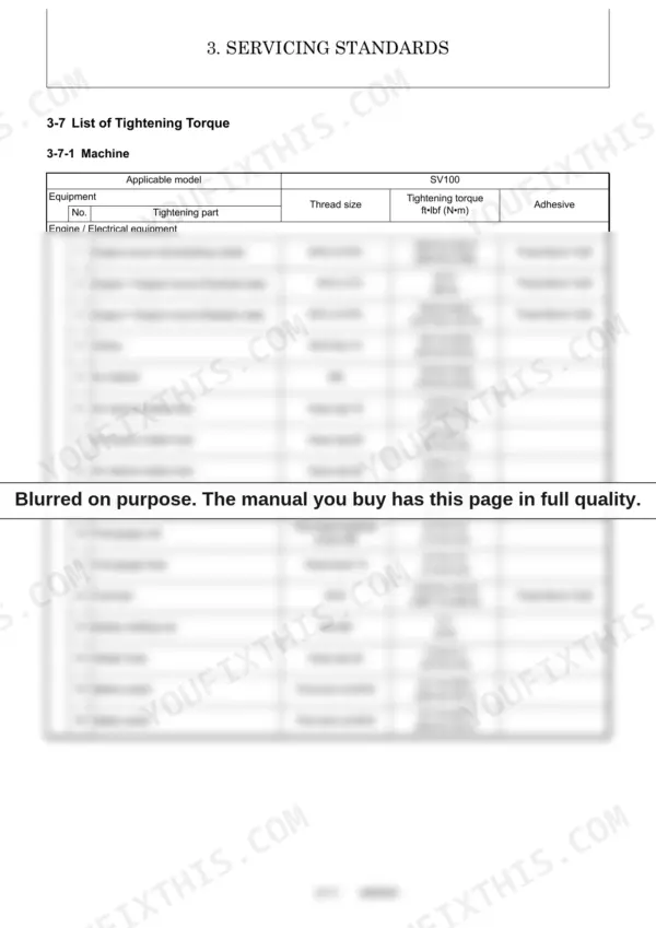
| Service Standards | 39-60 | Machine Performance, Engine Standards, Undercarriage (Rubber Crawler, Steel Crawler), Controls, Hydraulic Equipment Cylinders, Implement and Front Attachments, Tightening Torque List |
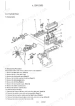
| Engine | 61-190 | General, Troubleshooting, Inspection and Adjustment, Engine Body, Lubrication System, Cooling System, Fuel Injection Pump/Governor, Turbocharger Disassembly and Reassembly, Starting Motor, Alternator, Special Service Tools, Service Standards |
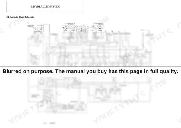
| Hydraulic System | 191-225 | Control Valve Operation, Hydraulic Circuit Schematic, Circuit Operation (Boom/Arm/Bucket/Swing/Blade/Travel), Non-Deviation Travel, Simultaneous Operations, Hydraulic PTO, Quick Coupler, Pressure Adjustment, Relief Valves, Swing Brake Valve, Cut-Off Valve |
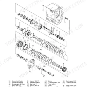
| Hydraulic Equipment | 226-384 | Hydraulic Pump, Control Valve and Spool Sections, Relief Valves, Pilot Valve, Swing Motor, Travel Motor (Specifications/Troubleshooting/Disassembly/Assembly), Pilot Check Valve |
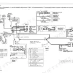
| Adjustment and Repair | 385-492 | Electrical Equipment Layout, Monitor and Alarm Systems, Wiring Diagram, Engine Removal/Reinstallation, Starter and Radiator Service, Undercarriage (Front Idler/Track Roller/Carrier Roller), Controls Adjustment, Swing Bearing, Hydraulic Equipment Removal, Swivel Joint Disassembly, Hydraulic Cylinders, Piping Layout, Implement, Air Conditioner |
| Periodic Inspection and Servicing | 493-496 | Periodic Inspection and Servicing Schedule |
| Fuel, Lube Oil and Grease Recommended | 497-500 | Fuel Specifications, Lubricating Oil Specifications, Grease Recommendations |
| Troubleshooting | 501-540 | Non-Breakdowns (Bucket Release, Arm Movement, Travel Motor, Boom Swing, Oil Level Fluctuation, Quick Coupler), Machine and Engine Troubleshooting, Electrical Equipment on Panel |
| Reference Data | 541-546 | Specifications for Attachments |
Quick Reference Specifications
| Specification | Value | Page |
|---|---|---|
| Track roller M20 bolt tightening torque | 274.9 to 296.6 ft•lbf (372.7 to 402.1 N•m) | p. 57 |
| Fuel filter filtration area | 775 (5000) sq.in. (sq.cm) | p. 32 |
| Fuel filter element replacement interval | Every 250 hours | p. 93 |
| Suction filter filtration area | 338 (2180) sq.in. (sq.cm) | p. 30 |
| Return filter filtration accuracy | 10 µ | p. 30 |
| Air cleaner filtration area | 11.8 (1.1) sq.ft. (sq.m) | p. 32 |
| Air cleaner element replacement interval | Every 250 hours | p. 93 |
| Fan belt size | A42 | p. 32 |
| Fan belt tension (New part) | 0.276 to 0.354 (7 to 9) in. (mm) | p. 182 |
| Thermostat valve opening temperature | 157 to 163 (69.5 to 72.5) °F (°C) | p. 182 |
| Starter motor pinion projection voltage | 8.0 or less V | p. 151 |
| Starter motor installation bolt (M12) tightening torque | 57.9 to 72.3 ft•lbf (78.5 to 98.1 N•m) | p. 407 |