
Part of the Case Repair Manuals.
Case printed this bound set of shop sections in England for the 585, 685, 595 and 695 tractors. It gives you the numbers you can't guess: 12 degrees static timing on the 585, 16 on the 685, and 0.012 in hot valve clearance on both.
A job on these tractors usually stalls for want of one number. The gauge is teed into the steering circuit and nobody knows what a good reading is. Section 8001 gives it: 2050 to 2150 psi with the engine running. The same book also covers the Bosch VE and VA pumps, synchromesh and power shift gearboxes, ZF and Carraro MFD axles, and cab air conditioning.
Print the section you need and take it to the bench. Let it collect oil and thumbprints while you get the tractor back in the field before the weather turns.
Other edition of this manual
What's Inside This Case 585, 685, 595, 695 Manual
| System | Pages | Key Topics |
|---|---|---|
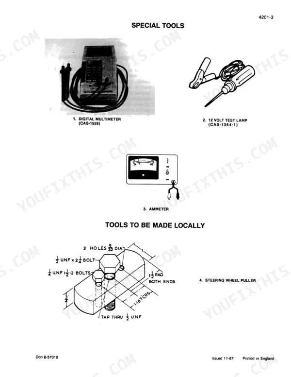
| General | 5-92 | General Specifications, Special Tools, Fuel System Specifications, Steering System Specifications, Hydraulic System Specifications |
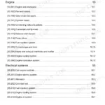
| Engines | 93-404 | Engine Removal, Engine Troubleshooting, Separating the Tractor, Cylinder Head (4-Cylinder), Valves and Rockers, Cylinder Block, Pistons and Conrods, Camshaft and Idler Gear, Crankshaft, Bearings and Balancer, Lubrication System, Engine Cooling System |
| Fuel System | 405-528 | Fuel Injection Pump VE, Fuel Injection Pump VA, Fuel Injectors, Fuel Tanks for Tractors with XL Cab |
| Electrical | 529-829 | Electrical Troubleshooting and Schematics, Electrical System Troubleshooting, Wiring Diagrams for Tractors with and Without XL Cab, Battery Servicing and Testing, Lucas A115, A127 and A133 Alternators and Regulators, Starter Motors |
| Steering | 830-979 | Steering Pump Removal, Steering Hand Pump, 2WD Front Axles, Cast Heavy Duty Fixed Front Axle, Steering Cylinders for 2WD, MFD and Cast Axle |
| Power Train - Clutch, Rear Axle and Transmissions | 980-1457 | Clutch Controls, Linkage and Release Bearing, Rear Axle, Rockford Engine Clutch and Flywheel, Steering Support Removal, Synchromesh Speedbox, Rangebox with Light and Heavy Duty Park Brake, Power Shift Transmission, Forward/Reverse Transmission, Differential |
| Power Train - PTO, Creeper and MFD Drive | 1458-1845 | PTO Clutch and Lower Shaft for 2WD and MFD, Laycock Engine Clutch, Speedbox and Rangebox Removal, Creeper Speed Transmission, Zf Apl 325, APL 330 and APL 335 MFD Front Axles, Carraro Axles and Drop Box, MFD Transfer Gearbox, MFD Drive Shaft |
| Brakes | 1846-1951 | Disc Brakes, Brake Master Cylinders and Controls, Park Brake for 2WD and MFD Tractors |
| Hydraulic System | 1952-2274 | Hydraulic Schematic and Troubleshooting, Hitch Adjustments, Multiple Control Valve (MCV), Unloading and Flow Control Valve, Filter and Pump, Bosch Remote Valves, Draft Cylinder and Rockshaft, Control Levers and Raise Rate Valve, Hydraulic Housing Removal |
| Chassis and Accessories | 2275-2548 | Pedal and Lever Adjustment, Air Conditioning Troubleshooting, Testing and Servicing, Hood, Fender and Panels, Cab Removal |
Quick Reference Specifications
| Specification | Value | Page |
|---|---|---|
| All Models | ||
| Diesel Engine Model | D 206 (585) / D 239 (685) | p. 16 |
| Rated Engine Speed | 2300 r/min | p. 16 |
| Static Timing (before top dead centre) | 12 Degrees (585) / 16 Degrees (685) | p. 16 |
| Displacement | 206 in3 (3 382 cm3) (585) / 239 in3 (3911 cm3) (685) | p. 16 |
| Valve Clearances (hot), Inlet and Exhaust | 0.012 in (0.30 mm) | p. 16 |
| Steering System Check pressure, engine running | 2050 to 2150 psi (141 to 148 bar) | p. 1957 |
| PTO spool and regulator valve pressure, fully engaged | 220 to 250 PSI (15 to 17 Bar) | p. 1984 |
| MFD pressure | 320 psi (22 bar) | p. 1962 |
| Rear Wheel Nuts torque | 205 to 220 lb ft (278 to 298 Nm) | p. 90 |
| 585 | ||
| Crankcase Capacity (including filter) | 16.2 UK pints / 2.5 U.S gal / 9.5 litre | p. 16 |
| Oil Pressure | 40 to 60 psi (275 to 414 kPa) | p. 16 |
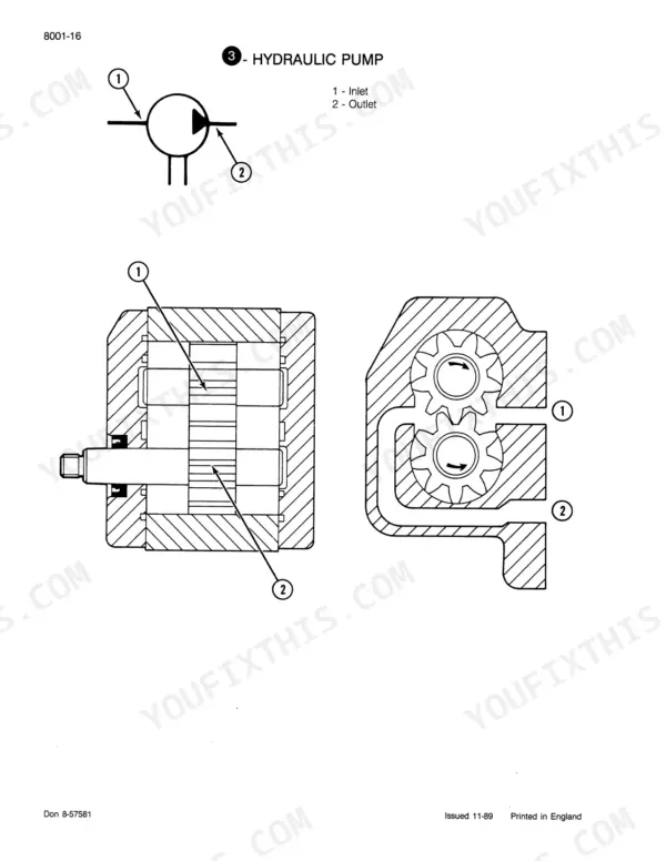
| Hydraulic Pump Output at 2300 r/min, 27 tooth drive gear | 10.6 UK or 12.7 U.S gal min (48.5 litre min) | p. 16 |
| PTO r/min at rated engine speed, Upper / Lower shaft | 580 / 1050 | p. 17 |
| 685 | ||
| Crank Case Capacity (including filter) | 2.5 U.S gal / 9.5 litres | p. 18 |
Case 585, 685, 595, 695 Common Problems This Manual Covers
PTO drops out or loses power under a heavy implement
Put a gauge on the PTO circuit before you split anything. With the PTO fully engaged, spool and regulator valve pressure should read 220 to 250 psi (15 to 17 bar). If pressure is low, chase the oil supply and the regulator. If pressure is good and the PTO still slips, the clutch pack is next. That work is in the PTO Clutch and Lower Shaft section.
Manual Section: PTO Clutch and Lower Shaft p. 1984Powershift (Hi-Lo) will not change range
Section 8001 starts with the voltage at the solenoid, and pressure must be 320 psi (22 bar). If the powershift still won't operate, check the electrical circuit, harness, toggle switch and powershift dump switch. When the electrics and pressure both check out, Section 6320 covers mechanical repair of the Power Shift Transmission.
Manual Section: Section 8001 Hydraulic Schematic and Troubleshooting / Section 6320 Power Shift Transmission p. 1960Three-point hitch lifts slowly or struggles with a mounted implement
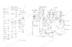
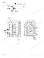
Run the pump check in Section 8001 first. Move the position control lever to maximum height and time the hitch lift rate. The fast response figure is 2 to 3 seconds. If it's slow, move on to the full pump efficiency and main relief valve test at the numbered test points. At 2300 r/min, a 585 pump should give 12.7 U.S gal/min with the 27 tooth drive gear. With the 20 tooth drive gear it should give 17.3 U.S gal/min.
Manual Section: Section 8001 Hydraulic Schematic and Troubleshooting p. 1956Engine cranks slowly and won't fire on a cold morning
Work through Problem 5 in the electrical troubleshooting chart. If the starter turns the engine below 200 rpm, test the battery and cables using Battery Servicing and Testing, then check the starter using Starter Motors. Next check the thermostart unit. If cranking speed is fine, the chart sends you to Section 2201 for fuel supply, air intake and internal engine faults.
Manual Section: Electrical System Troubleshooting p. 642Frequently Asked Questions
Steering goes heavy and the hitch turns slow once the PTO is running. Where do I start?
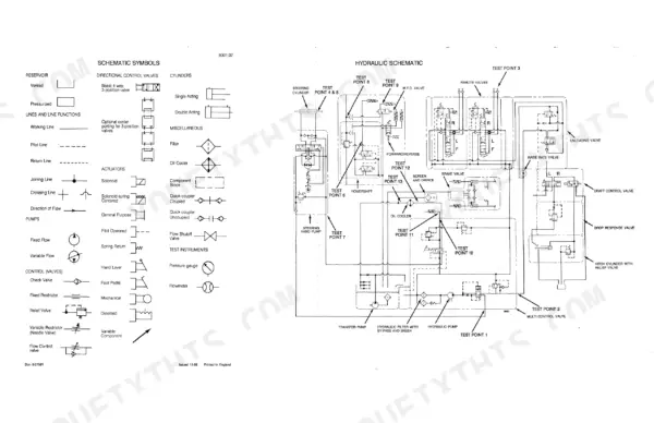
Start at the pump, not the steering cylinders. Section 8001 has you move the position control lever to maximum height and time the hitch lift rate. The fast response figure is 2 to 3 seconds. Then tee a gauge into the steering circuit. Section 8001 wants 750 to 1000 psi (51 to 68.9 bar) with the engine stopped and 2050 to 2150 psi (141 to 148 bar) running. The same section has a hydraulic schematic with numbered test points and a full pump efficiency and main relief valve test. That tells you whether the pump is really worn before you buy one. p. 1957
It only fires on a shot of ether. Is the injection pump timing out?
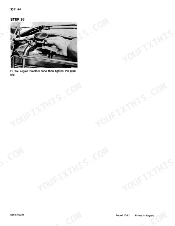
It could be, but check the cheap things first. Problem 5 in the electrical troubleshooting chart lists three causes. Fuel supply, air intake or internal engine faults send you to Section 2201. Cranking below 200 rpm points to the starter side. The third cause is the thermostart unit. Blocked fuel filters and a weak lift pump are common fuel supply faults on tractors this age. Static timing is 12 degrees BTDC on the 585 and 16 degrees on the 685. For the VE pump, Section 3311 puts a dial gauge on the pump plunger. You turn the crankshaft pulley until the gauge shows 0.039 in of plunger movement. p. 642
The MFD stays engaged and won't disengage. Is it the solenoid or the gearbox?
Do the two checks in Section 8001 before you pull the transfer box. First check the voltage at the solenoid. Then read MFD pressure, which should be 320 psi (22 bar). An electrical fault sends you to Section 4001. Mechanical damage in the drive box sends you to Section 6475 or 6480 for the MFD transfer gearbox. The book also covers the ZF APL 325, 330 and 335 front axles, the Carraro axle and the MFD drive shaft. p. 1962
Does the book give engine and capacity figures for the 595 and 695?
No, and you should know that before you order. The General Specifications tables only print data for the 385, 485, 585, 685 and 885. The 585 and 685 figures are there. The 585 runs the D 206 at 206 cu in with 9.5 litres of crankcase oil including the filter. The 685 runs the D 239 at 239 cu in, also 9.5 litres. A few sections are written for 95 Series tractors, including electrical schematics, the creeper transmission and forward/reverse on XL models. p. 16
Are there wiring diagrams for both cab and non-cab tractors?
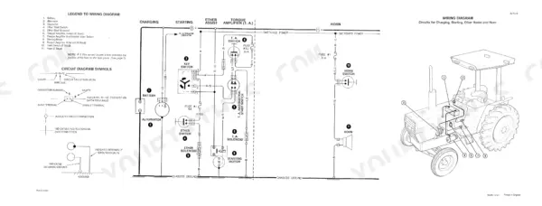
Yes. Section 4210 is the wiring diagram for tractors without a cab, and Section 4225 covers 85 Series XL tractors. Section 4001 has the schematic circuits for 95 Series tractors. Battery servicing and testing, Lucas alternators and regulators, and starter motors each get their own section. These tractors have no fault codes. You fault-find with a meter, the diagram and a wire you can trace. p. 734







Reviews
There are no reviews yet.