

Part of the Case Operator Manuals.
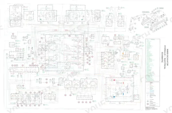
Hunting for a Case 9060B service manual PDF that came from the factory, not a forum? All 803 pages of this Case Service Manual (OEM #7-65272) cover the 9060B Excavator in both its Mitsubishi and Cummins engine versions. You get foldout electrical and hydraulic schematics, pressure checks with relief valve adjustment procedures, and complete teardown steps for the main pump, control valve, and boom, arm, and bucket cylinders. Inside: a full troubleshooting section that walks you from symptom to root cause on both the electrical and hydraulic sides. Set the lower track roller cap screws at 550 to 643 lb-ft (746 to 872 Nm), and swap the fuel filter every 500 hours. A dead 9060B burns money every hour it sits. Bookmarked PDF, opens on any device; carry the tablet to the machine and get wrenching.
What's Inside This Manual
| System | Pages | Key Topics |
|---|---|---|
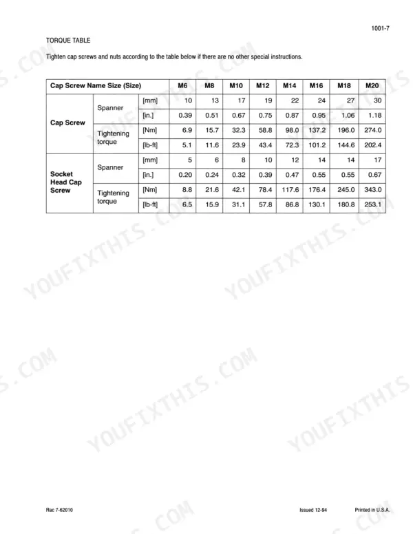
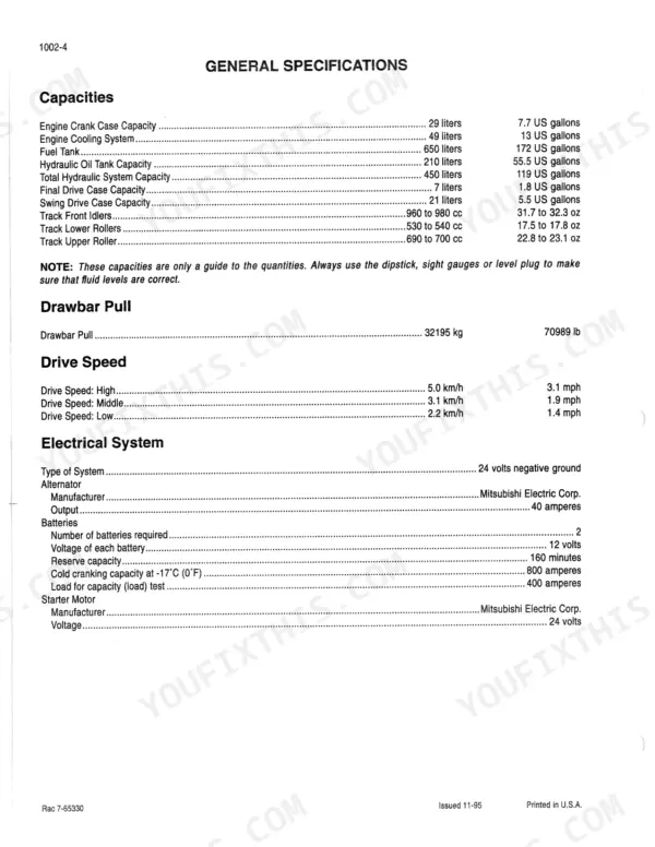
| General | 3-26 | Loctite Product Chart, Safety, General Information and Torque Specifications, Specifications |
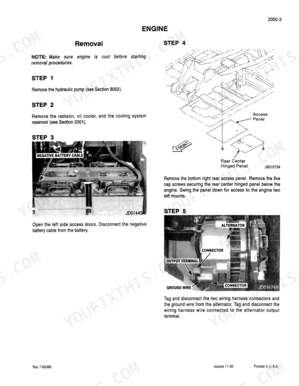
| Engine | 27-92 | Engine - Mitsubishi, Engine - Cummins, Radiator, Oil Cooler and Cooling System Reservoir - Mitsubishi Engine, Oil Cooler and Cooling System Reservoir - Cummins Engine |
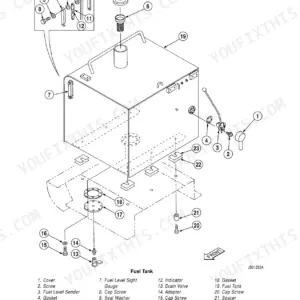
| Fuel System | 93-110 | Fuel Tank, Filters and Lines - Mitsubishi Engine, Filters and Lines - Cummins Engine |
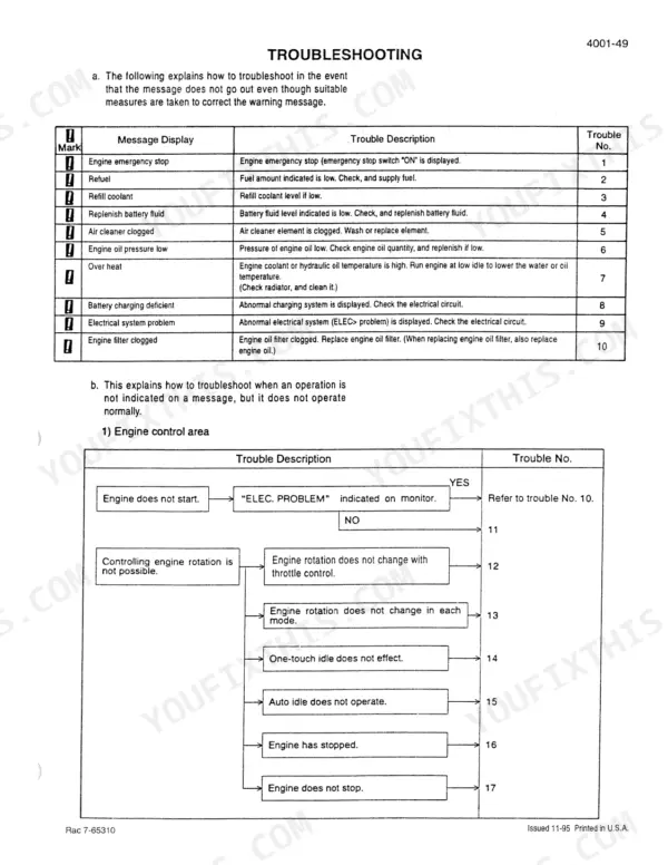
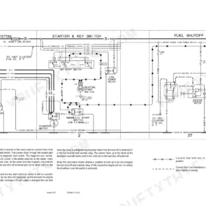
| Electrical | 111-188 | Electrical Specifications and Troubleshooting, Electrical Schematic Foldout, Battery Testing, Maintenance and Booster Battery Connections, Controller |
| Tracks | 189-248 | Rollers and Idlers |
| Power Train | 249-282 | Drive Motor and Final Drive Transmission, Swing Motor and Swing Reduction Gear |
| Cleaning the Hydraulic System | 283-292 | Hydraulic System Cleaning, Contamination Types, Portable Filter Usage, System Flushing |
| Hydraulic Specifications, Troubleshooting and Pressure Checks | 293-354 | Hydraulic Specifications, Component Locations, Pressure Testing, Relief Valve Adjustments, Travel Motor Drain Measurement |
| Main Hydraulic Pump | 355-378 | Main Pump Removal, Pump Coupling, Pilot Pump, Pump Installation |
| Main Hydraulic Control Valve | 379-394 | Control Valve Removal, Control Valve Installation, Manifold Connections |
| Cylinders | 395-442 | Boom Cylinder, Arm Cylinder, Bucket Cylinder, Cylinder Disassembly, Cylinder Assembly |
| Hand Control Valves, Foot Left and Right Travel Control Valves, Foot Straight Travel Control Valve, Shuttle Valve and Accumulator | 443-504 | Hand Control Valves, Travel Control Valves, Shuttle Valve, Accumulator Testing, Accumulator Removal |
| Eight Spool Solenoid Valve, Swing Lock and Swing Brake Solenoid Valve | 505-536 | Eight Spool Solenoid Valve, Swing Brake Release Solenoid, Free Swing Solenoid Valve, Solenoid Testing |
| Cushion Control Valve, Auxiliary Hydraulics, Hydraulic Reservoir Pressurization System, Oil Cooler and Fan Drive Motor Hydraulic Pump, Hydraulic Pilot Filter, Hydraulic Inline Filter and Bypass Oil Filter, Hydraulic Swivel | 537-636 | Cushion Control Valve, Auxiliary Hydraulics, Reservoir Pressurization, Oil Cooler, Fan Drive Pump, Hydraulic Filters, Hydraulic Swivel |
| Mounted Equipment | 637-801 | Upper Structure Counterweight, Boom, Arm and Bucket, Operators Seat, Operators Seat Bracket and Seat Belts, Cab and Cab Equipment, Air Conditioner Troubleshooting and System Checks |
| Electrical and Hydraulic Schematic Foldouts | 802-803 | Electrical Schematic Foldout, Hydraulic Schematic Foldout |
Quick Reference Specifications
| Specification | Value | Page |
|---|---|---|
| Fuel Filter replacement interval | every 500 hrs | p. 94 |
| Lower Track Roller Cap Screws | 550 to 643 lb-ft (746 to 872 Nm) | p. 194 |
| Upper Carrier Roller Cap Screws | 181 to 210 lb-ft (245 to 285 Nm) | p. 194 |
| Track Roller Weight (Inner Track Roller) | 153 pounds (69.6 kg) | p. 193 |
| Track Roller Weight (Outer Track Roller) | 156 pounds (70.8 kg) | p. 193 |
| Socket head cap screws that hold the split flanges to ports P1 and P2 | 72 to 87 lb-ft (98 to 118 Nm) | p. 250 |
| Hydraulic pilot filter element replacement interval | every 1000 hrs (initially at 50 hrs) | p. 605 |
| Hydraulic inline filter element replacement interval | every 1000 hrs (initially at 50 hrs) | p. 605 |
| Fuel Tank Capacity | 650 liters | p. 104 |
| Operating Weight (with 3.36m arm) | 44985 kg | p. 24 |
| Fuel Tank Mounting Cap Screws Torque | 180 lb-ft | p. 94 |
| Track Shoe Cap Screws Torque | 587 to 716 lb-ft | p. 193 |