
Part of the Case IH Repair Manuals.
This is Case IH service manual 48144050, 2nd edition, August 2017. It covers the Axial-Flow 7240, 8240 and 9240 Tier 4B (final) combines for North America, PIN YEG227001 to YHG235000.
It covers the FPT Cursor 11, 13 and 16 engines with SCR, plus the rotor gearbox, hydrostatic drive, hydraulics, tracks, cab and electrical systems. It also follows the crop all the way from the feeder to the unload auger. This book gives you the factory figures.
The chapters run system by system. Fault codes have their own chapter, and the fold-out electrical and hydraulic schematics are at the back.
What's Inside This Case IH Axial-Flow 7240, Axial-Flow 8240, Axial-Flow 9240 Manual
| System | Pages | Key Topics |
|---|---|---|
| Introduction, Safety and Specifications | 1-48 | Safety, Torque, Capacities, Dimensions, General Specification, Machine Specification |
| Engine | 49-354 | Engine and Crankcase, Air Cleaners, Fuel Tanks, Lubrication, Cooling, Fan Drive, Air Compressor, SCR |
| Main Gearbox and Rotor Drive | 355-434 | Main Gearbox, Main Clutch, Feeder Housing Pump, Threshing Pump, Fan Pump, Slip Clutch |
| Transmission | 435-548 | Mechanical Transmission, Hydraulic Components, External Controls, Differential |
| Front and Rear Axles | 549-670 | Powered Front Axle, Final Drive, Knuckles, Powered Rear Axle, Non-Powered Rear Axle |
| Hydrostatic Drive | 671-846 | Hydrostatic Control, Two-Speed, Pump, Motor, Rear Hydrostatic |
| PTO and Brakes | 847-906 | Front PTO, Parking Brake, Service Brakes |
| Hydraulic Systems | 907-1178 | Pump, Main Control Valve, Header Height, Unload, Reel, Fan Drive, Chaff Spreader |
| Steering and Wheels | 1179-1282 | Steering Control, Tie Rods, Cylinders, Autoguidance, Front Wheels |
| Tracks and Track Suspension | 1283-1444 | Rubber Track, Track Rollers, Idler Wheel, Tension Cylinder, Track Frame |
| Cab Climate Control | 1445-1528 | Air-Conditioning Compressor, Evaporator, Condenser, Expansion Valve, Heater Core |
| Electrical System Overview and Control Systems | 1529-2351 | Display Diagnostic Screens, Sensors, Fuel Injection, Engine Control, Transmission Control, HVAC Control |
| Harnesses, Connectors and Electrical Schematics | 2352-3961 | Electrical Schematic Sheet, Harness, Connector, Fuses, Relays |
| Electrical Component Systems | 3962-4495 | Starting, Alternator, Battery, Lighting, Feeding Control, Header Height, Autoguidance, SCR Electrical |
| Fault Codes (DTC) | 4496-7350 | Alarm Codes, DTC, Engine, Ucm, Failure Modes |
| Product Feeding | 7351-7510 | Floating Roll, Feeder Housing, Stone Trap, Header Drive, Feeder Drive |
| Threshing and Separation | 7511-7652 | Concave, Concave Control, Rotor Drive, Rotor, Separator Grates |
| Residue Handling | 7653-7780 | Straw Chopper, Chopper Drive, Chopper Clutch, Straw Spreader |
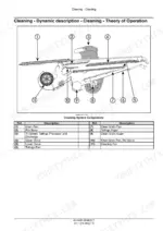
| Cleaning | 7781-7916 | Self-Leveling, Grain Pan, Upper Shoe, Lower Shoe, Fan, Tailings |
| Grain Tank and Unloading | 7917-8184 | Clean Grain Elevator, Grain Tank, Unload Drive, Unload |
| Platform, Cab, Bodywork and Special Tools | 8185-8363 | Hood, Shields, Mirrors, Seat, Cab, Special Tools |
| Electrical and Hydraulic Schematic Foldouts | 8364-8391 | Starting and Charging, LIN Networks, Power Distribution, Hydrostatic Ground Drive, Rotor Drive Pump |
Quick Reference Specifications
| Specification | Value | Page |
|---|---|---|
| Engine (7240 / 8240 / 9240) | FPT Cursor 11 / FPT Cursor 13 / FPT Cursor 16 | p. 46 |
| Gross power, ISO TR14396 (7240 / 8240 / 9240) | 300 kW (403 Hp) / 358 kW (480 Hp) / 410 kW (550 Hp) | p. 46 |
| Peak power with power rise (7240 / 8240 / 9240) | 349 kW (469 Hp) / 414 kW (555 Hp) / 466 kW (625 Hp) | p. 46 |
| Rated speed | 2100 RPM | p. 46 |
| Cylinder displacement (7240 / 8240 / 9240) | 11.1 L (677 in³) / 12.9 l (787 in³) / 16 L (970 in³) | p. 46 |
| Battery | 2 x 12 V - 950 CCA | p. 46 |
| Alternator | 185 A 12 V | p. 46 |
| Engine oil, FPT Cursor 11 | 26 L (6.9 US gal) | p. 29 |
| Engine oil, FPT Cursor 13 | 28 L (7.4 US gal) | p. 29 |
| Engine oil, FPT Cursor 16 | 32 L (8.5 US gal) | p. 29 |
| Hydraulic system total capacity (7240, 8240 / 9240) | 65.2 L (17.2 US gal) / 68.2 L (18 US gal) | p. 45 |
| Traction gearbox oil | 19 l (5 US gal) | p. 29 |
| Rotor gearbox oil | 7 l (1.8 US gal) | p. 29 |
| Rotor diameter | 762 mm (30 in) | p. 37 |
| Rotor length | 2623 mm (103.3 in) | p. 37 |
| Cleaning fan speed range | 300 - 1150 RPM | p. 39 |
| PFC pump high pressure standby | 207 - 214 bar (3000 - 3100 psi) | p. 910 |
| Reel drive relief | 145 bar (2102 psi) | p. 910 |
| Feeder lift cylinder thermal relief | 276 bar (4002 psi) | p. 910 |
| Final drive locknut torque | 1300 Nm (959 lb ft) | p. 599 |
Case IH Axial-Flow 7240, Axial-Flow 8240, Axial-Flow 9240 Common Problems This Manual Covers
Feeder house and header leak down during harvesting
The limit is no more than one inch of lift cylinder travel per hour. Check the lift cylinder lines first, and repair or replace any line that is visibly leaking. If the lines are dry, look for leaks at the feeder lift valve and replace its O-rings.
Manual Section: Header or attachment height system - Troubleshooting p. 1068Air compressor continuously cycles
Look for an air leak at the governor first, and use the governor manufacturer's manual for its maintenance and troubleshooting steps. Next, inspect the connection between the governor and the compressor and repair any leak there. If both are tight, drain the reservoir to clear out excessive contamination.
Manual Section: Air compressor - Check p. 296Separator disengages while harvesting, display shows alarm A-0100 and then shuts off
The separator disengages while harvesting for no known reason, and the display shows the disengage separator alarm (A-0100) before it shuts off. Re-calibrate the chopper speed shift actuator using the procedure under Harvest material flow control system - Calibrate - Chopper speed shift actuator.
Manual Section: Harvest material flow control system - Troubleshooting p. 4161DTC 1113 - Engine coolant temperature sensor voltage is higher than expected
ECU A-9000 has seen more than 4.93 V on the B-9003 signal circuit. First verify the fault is present and active. The possible failure modes are faulty B-9003 wiring, a B-9003 internal failure, or faulty A-9000 software.
Manual Section: Fault codes p. 4562Frequently Asked Questions
Which Case IH combines and serial ranges does this service manual cover?
It covers the Axial-Flow 7240, 8240 and 9240 Tier 4B (final) combines built for North America. The three PIN ranges are YEG227001 to YFG230000, YFG230001 to YGG233000 and YGG233001 to YHG235000. It is part number 48144050, 2nd edition in English from August 2017, and it replaces part number 47800117. p. 1
What engines and power ratings do the 7240, 8240 and 9240 have?
The 7240 runs an FPT Cursor 11, the 8240 a Cursor 13 and the 9240 a Cursor 16. Gross power (ISO TR14396) is 300 kW (403 Hp), 358 kW (480 Hp) and 410 kW (550 Hp). With power rise, peak power is 349 kW (469 Hp), 414 kW (555 Hp) and 466 kW (625 Hp). All three are rated at 2100 RPM. Displacement is 11.1 L (677 in³), 12.9 l (787 in³) and 16 L (970 in³). p. 46
What are the engine oil and hydraulic fluid capacities of the Axial-Flow 7240, 8240 and 9240?
Engine oil takes 26 L (6.9 US gal) on the Cursor 11, 28 L (7.4 US gal) on the Cursor 13 and 32 L (8.5 US gal) on the Cursor 16. Total hydraulic system capacity is 65.2 L (17.2 US gal) on the 7240 and 8240, and 68.2 L (18 US gal) on the 9240. The traction gearbox holds 19 l (5 US gal) and the rotor gearbox holds 7 l (1.8 US gal). p. 29
Does the manual list fault codes and alarm codes?
Yes. The FAULT CODES chapter covers display alarm codes such as A-0046 Feeder Speed LOW, where the action is to increase feeder speed. It also covers engine control unit DTCs such as 1113 for coolant temperature sensor voltage, and module codes such as E0059-05 for a disconnected header type sensor line on UCM1. Each entry gives the control module, context, cause, possible failure modes and solution. p. 4562
Does it include wiring diagrams and hydraulic schematics?
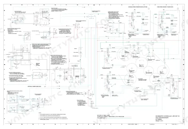
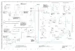
Yes. The electrical chapter has electrical schematic sheets with harness and connector pages, plus the fuses and relays. Fold-out electrical and hydraulic schematics are at the back of the book. The fold-outs come in separate sets by PIN range, for example PIN YFG230001 and above and PIN YHG235001 and above, so check your serial plate before you trace a circuit. p. 8373






Reviews
There are no reviews yet.