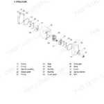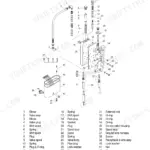



Part of the Hyundai Repair Manuals.
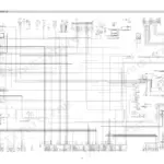
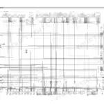
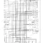
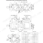
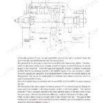
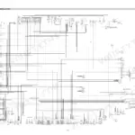
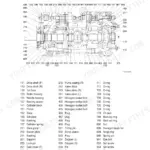
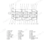
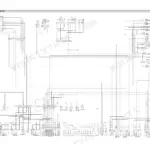
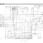
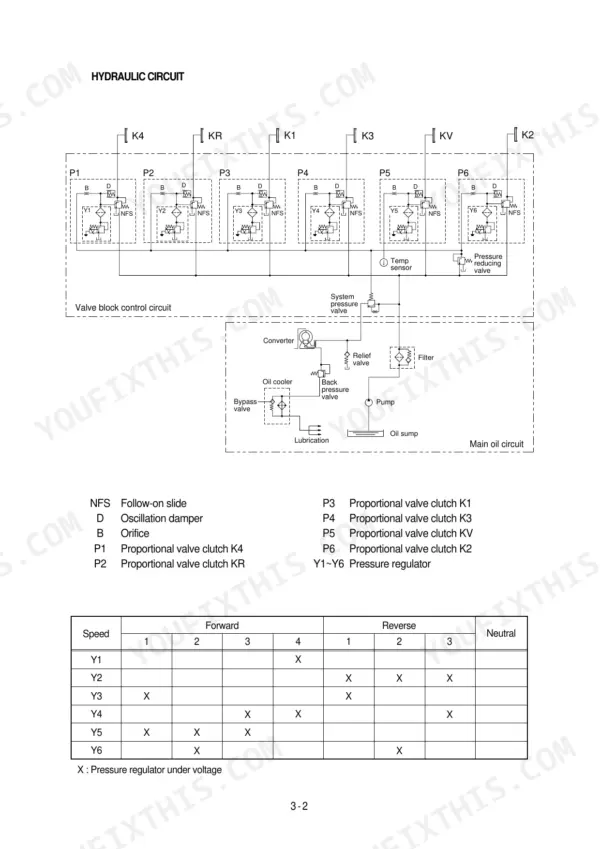
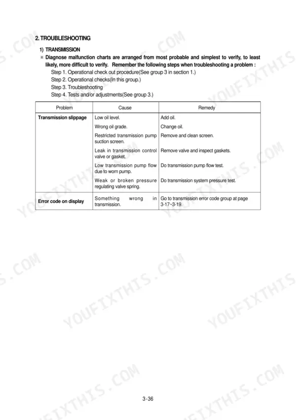
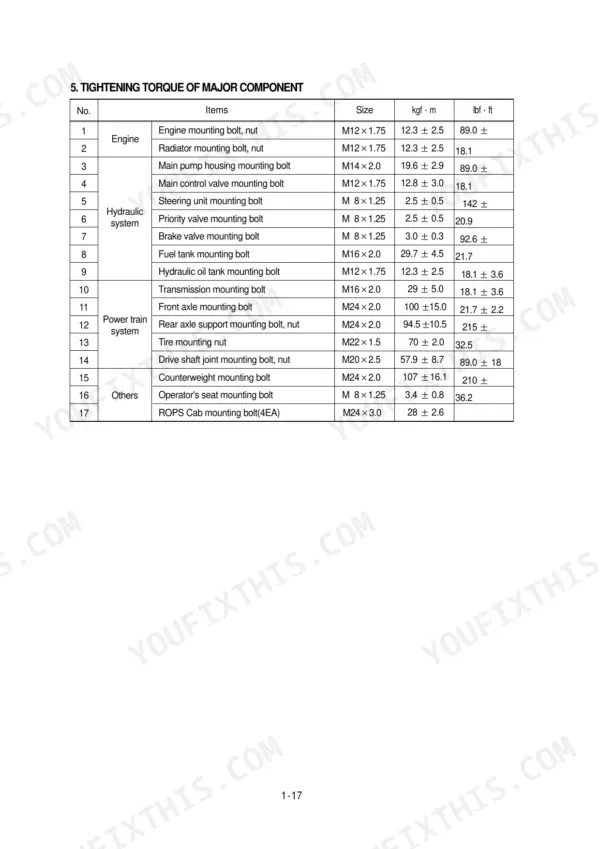
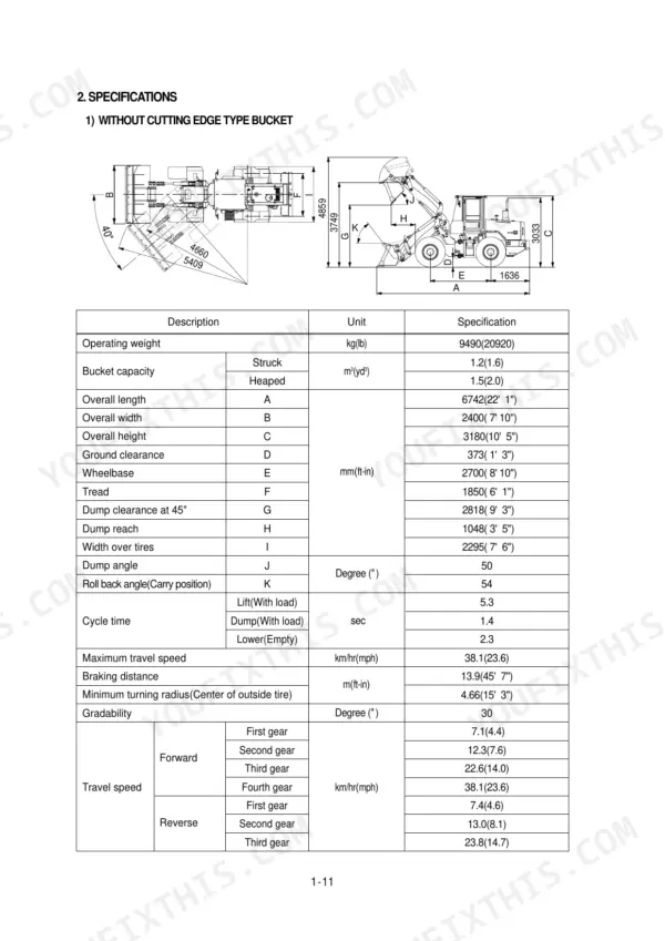
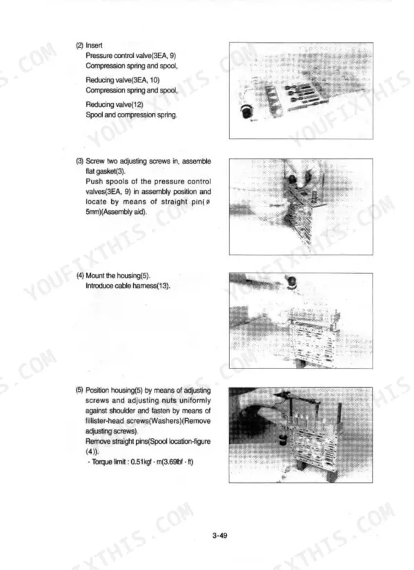
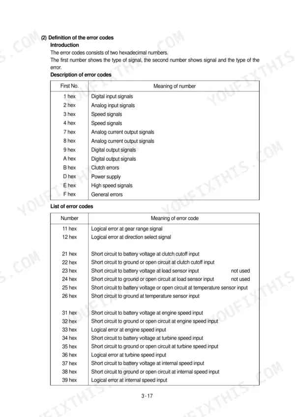
Need factory answers for your Hyundai HL730TM-3 wheel loader? This 455-page Hyundai HL730TM-3 service manual PDF walks through every major system: torque converter, transmission with electro-hydraulic shift control, brake and steering circuits, work equipment hydraulics, and the full electrical system. Inside you get complete wiring diagrams with component location charts, hydraulic schematics for the steering and work equipment circuits, a full troubleshooting section, and page after page of disassembly and assembly procedures. Every circuit is drawn out, from the priority valve to the charging system. The main pump runs a maximum operating pressure of 215 kgf/cm²; torque the engine mounting bolts to 12.3 ± 2.5 kgf·m. No more chasing shift faults with a multimeter and a prayer. Bookmarked for quick jumps; search any spec by keyword and pull it up on your phone right at the machine.
What's Inside This Manual
| System | Pages | Key Topics |
|---|---|---|
| General | 9-31 | Safety Hints, Follow Safe Procedure, Wear Protective Clothing, Warn Others of Service Work, Use Handholds and Steps, Prepare for Emergencies, Work in Clean Area |
| Engine | 32-35 | Structure and Function, Lube Oil Circuit Schematic, Fuel System Schematic, Cooling System Schematic |
| Power Train System | 36-184 | Structure and Function (Power Train Component Overview), Torque Converter, Transmission, Electro-Hydraulic Shift Control with Proportional Valve, Gear Selector |
| Brake System | 185-223 | Structure and Function (Outline), Brake Pump (Principle of Operation), Brake Valve (Operation) |
| Steering System | 224-288 | Structure and Function (Outline), Hydraulic Circuit, Priority Valve, Steering Unit, Overload Valve, Steering Cylinder |
| Work Equipment | 289-379 | Structure and Function (Hydraulic System Outline), Hydraulic Circuit, Work Equipment Hydraulic Circuit, Main Pump Operation, Remote Control Valve |
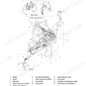
| Electrical System | 380-455 | Component Location (Location 1), Location 2, Electrical Circuit, Illumination Circuit, Head Light Circuit, Work Light Switch, Starting Circuit, Fuel Shut Off Circuit |
Quick Reference Specifications
| Specification | Value | Page |
|---|---|---|
| Engine mounting bolt, nut | 12.3 ± 2.5 kgf·m | p. 25 |
| Radiator mounting bolt, nut | 12.3 ± 2.5 kgf·m | p. 25 |
| Main pump maximum operating pressure | 215 kgf/cm² | p. 22 |
| Brake pump maximum operating pressure | 150 kgf/cm² | p. 23 |
| Overload relief valve pressure (Raise, roll back) | 240 kgf/cm² | p. 23 |
| Overload relief valve pressure (Dump) | 120 kgf/cm² | p. 23 |
| Main relief valve pressure | 215 kgf/cm² | p. 23 |
| Pressure reducing valve (pilot pressure) | 9 bar | p. 49 |
| Engine Oil Quantity | 14.0 L | p. 22 |
| Main Pump Capacity | 33+29 cc/rev | p. 22 |
| Transmission Oil Capacity | 20 L | p. 28 |
| Boom Cylinder Bore/Rod/Stroke | 105/65/710 mm | p. 23 |