
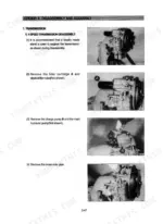
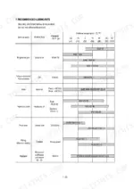

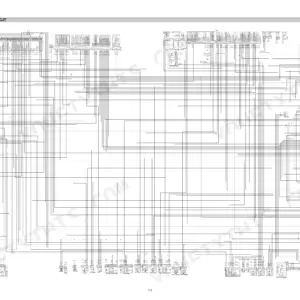
Part of the Hyundai Repair Manuals.
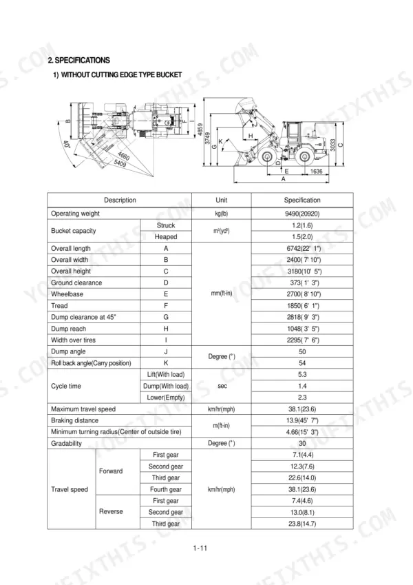
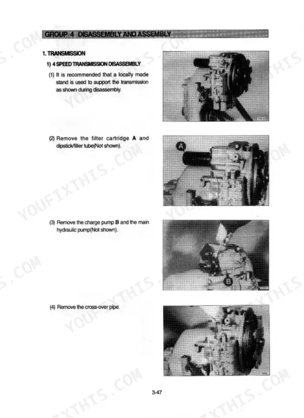
Need factory answers for your Hyundai HL740TM-3? This 450-page service manual PDF covers the Cummins B5.9-C powered wheel loader front to back, from power train and brakes to steering and work equipment. You get full electrical circuit diagrams with connector and component locations, hydraulic schematics with complete fluid routing, and page after page of step-by-step disassembly and assembly procedures for every major system. A dedicated troubleshooting section walks you through operational checks before you start pulling parts, so you diagnose first and wrench second. Torque the engine mounting bolts to 57.9 ± 8.7 kgf·m and set the main relief pressure at 220 kgf/cm², straight from the factory spec tables. No more chasing wiring faults with a multimeter and a prayer. Bookmarked with a full text layer; jump to any section or search any spec by keyword and get back to work.
What's Inside This Hyundai HL740TM-3 Manual
| System | Pages | Key Topics |
|---|---|---|
| Conversion Table | 3-8 | Millimeters to Inches, Kilogram to Pound, Liter to Gallon, kg·m to lb·ft, Kg/Cm² to Lb/in², Fahrenheit-Centigrade Conversion |
| General | 9-17 | Safety Hints |
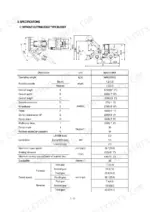
| Specification | 18-31 | Major Components, Engine, Main Pump, Brake Pump, Main Control Valve, Dynamic Power Transmission Devices |
| Engine | 32-38 | Structure and Function |
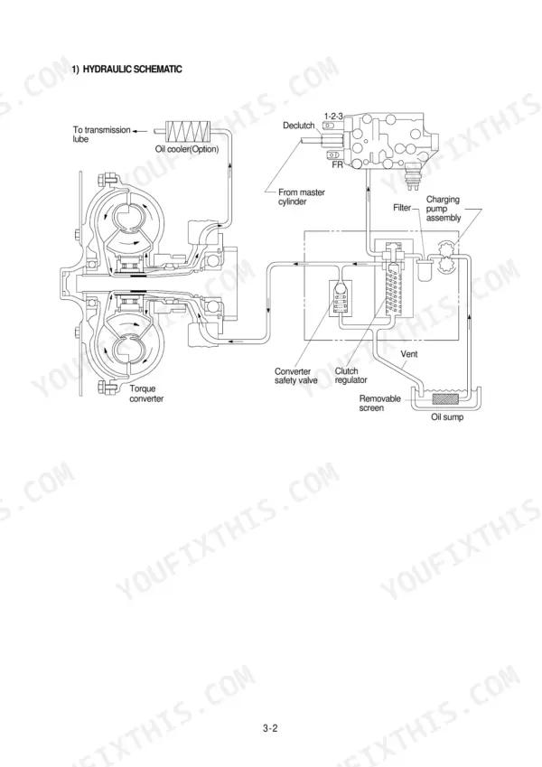
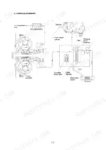
| Power Train System | 39-174 | Structure and Function, Operational Checks and Troubleshooting, Disassembly and Assembly |
| Brake System | 175-213 | Structure and Function, Operational Checks and Troubleshooting, Disassembly and Assembly |
| Steering System | 214-279 | Structure and Function, Operational Checks and Troubleshooting, Disassembly and Assembly |
| Work Equipment | 280-372 | Structure and Function, Operational Checks and Troubleshooting, Disassembly and Assembly |
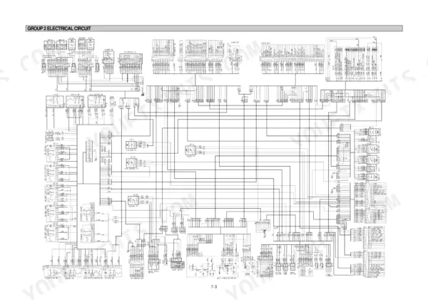
| Electrical System | 373-450 | Component Location, Electrical Circuit, Connectors, Troubleshooting |
Quick Reference Specifications
| Specification | Value | Page |
|---|---|---|
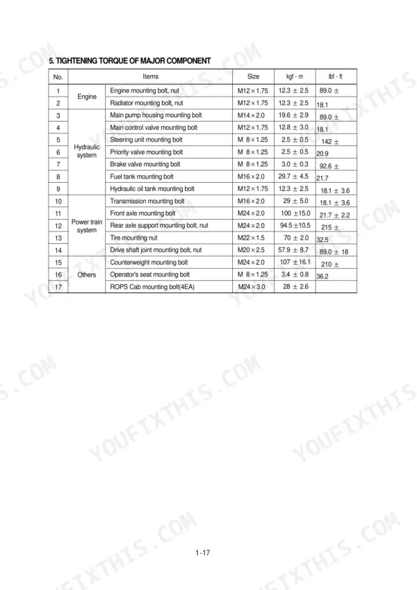
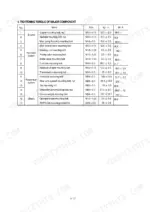
| Engine mounting bolt, nut | 57.9 ± 8.7 kgf·m | p. 25 |
| Radiator mounting bolt, nut | 12.3 ± 2.5 kgf·m | p. 25 |
| Main pump maximum operating pressure | 220 kgf/cm² | p. 22 |
| Brake pump maximum operating pressure | 150 kgf/cm² | p. 23 |
| Main control valve main relief valve pressure | 220 kgf/cm² | p. 23 |
| Main control valve overload relief valve pressure | 240 kgf/cm² | p. 23 |
| Remote control valve minimum operating pressure | 3.7 kgf/cm² | p. 23 |
| Remote control valve maximum operating pressure | 30 kgf/cm² | p. 23 |
| Speed 5km/hr | 5km/hr | p. 60 |
| Relief pressure | 20.5~21.5 MPa (205~215 bar, 3200~3300 psi) | p. 240 |
| Overload valve hexagon socket screws torque | 6.6+0.5 kgf m (47.7+3.6 lb ft) | p. 269 |
| Bypass valve set pressure | 1.36kg/cm2 (19.3psi) | p. 319 |
Hyundai HL740TM-3 Common Problems This Manual Covers
Hyundai HL740TM-3 steering wheel heavy and slow to respond, gets worse when hydraulic oil warms up
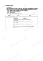
Check hydraulic oil level and condition before condemning parts. Test steering relief pressure against the spec on page 240; it must hold 20.5 to 21.5 MPa (205 to 215 bar). A low reading points to a clogged relief valve or weak pump output. Clean the relief valve first; it is far cheaper than a steering unit.
Manual Section: Steering System Troubleshooting p. 240No steering or hydraulic function at any engine speed, boom and bucket completely dead
Check hydraulic oil level first; a low tank starves steering and loader circuits together, and the tank holds 75 L (19.8 US gal). Verify main relief pressure reaches 220 kgf/cm2 as listed on page 23. If flow tests below the 17.5 GPM minimum on page 86, pull the pump for inspection.
Manual Section: Hydraulic System Troubleshooting p. 23Hydraulic oil foams and turns milky in the tank, pump whines under load
Drain and replace the oil if it looks milky; water contamination destroys the charge. Refill to the full mark, tank capacity is 75 L (19.8 US gal) per page 334. Inspect suction lines and fittings for air leaks, tighten loose clamps, and replace cracked hoses before aerated oil scores the pump.
Manual Section: Hydraulic System Troubleshooting p. 334Transmission stays in gear, dash shows no shift when selector column is moved
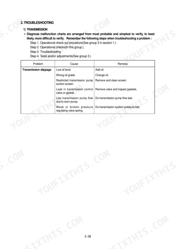
Check the connector and harness between the steering column controller and the transmission control unit; a lost signal stops shifting before anything mechanical fails. Work through the power train operational checks and troubleshooting starting on page 72. If the machine moves but feels weak, run a stall test; converter stall speed should read 2270 rpm per page 85.
Manual Section: Transmission Troubleshooting p. 72Engine oil pressure warning lamp flickers at idle then stays on when hot
Check the oil level immediately with the engine shut off; engine oil capacity is 16.4 L per page 22. Top up with the correct grade and restart. If the lamp stays on at proper level, verify actual pressure with a mechanical gauge and trace the sender circuit through the electrical section beginning on page 373.
Manual Section: Electrical Troubleshooting: Engine Oil Pressure Lamp p. 22Frequently Asked Questions
What are the torque specifications for the wheel loader components?
The tightening torque for major components is listed in the manual. For example, the engine mounting bolt and nut (M20x2.5) require 57.9 ± 8.7 kgf·m (419 ± 63 lbf·ft), and the counterweight mounting bolt (M30x2.0) requires 199 ± 29.9 kgf·m (1439 ± 216 lbf·ft). p. 25
What are the replacement specifications for the hydraulic pump?
The main hydraulic pump is a fixed displacement gear type pump. The maximum pump flow is 86 l/min (22.7 gpm) at 2200 ± 25 rpm and a test pressure of 220 ± 10 bar (3190 psi). p. 338
What is the procedure for bleeding the hydraulic brake system?
Two people are required to bleed the brake system. Put a clear plastic tube on bleed screw (B) to route fluid to a container (A). Push and hold the brake pedal down until the bleeding procedure is complete, opening the bleed screw on the differential and axle assembly until hydraulic oil starts to flow free of air. p. 206
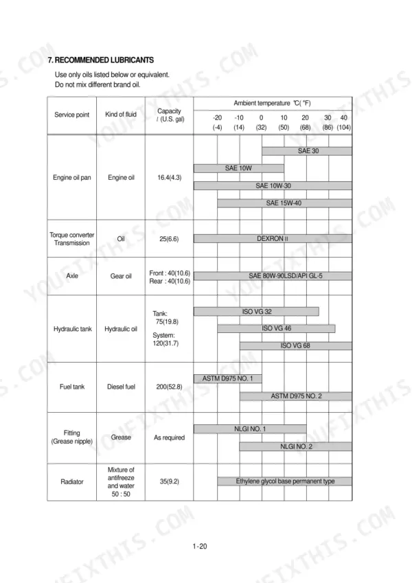
What is the recommended oil for the hydraulic tank?
The hydraulic tank capacity is 75 liters (19.8 U.S. gal) for the tank and 120 liters (31.7 U.S. gal) for the system. Depending on the ambient temperature, ISO VG 32, ISO VG 46, or ISO VG 68 oils are recommended. p. 28
What is the torque specification for the main control valve tie rod nuts?
When assembling the main control valve, final torque the two 11/16 nuts to 48 ± 5 lbf·ft and the 3/4 nut to 74 ± 8 lbf·ft. p. 361
Will this Hyundai HL740TM-3 Service Manual download right away?
A 450-page Service Manual in searchable PDF format, available the moment you complete checkout. View on computer, tablet, or phone, with no shipping wait.
Can I print this Hyundai HL740TM-3 manual?
Yes. Printing works from any reader and any printer, for your own shop use.








Reviews
There are no reviews yet.